
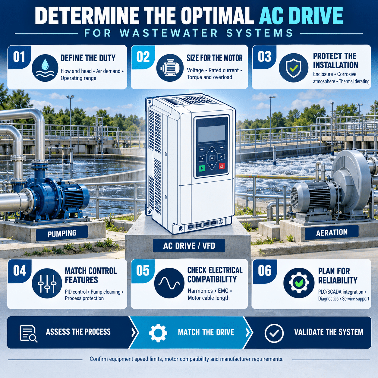
Wastewater treatment plants rely on motors to operate pumps, blowers, mixers, conveyors, screens and other essential equipment. These loads rarely need to run at full speed all the time. An AC drive, also known as a variable frequency drive or VFD, can adjust motor speed to match actual process demand.
The right drive can reduce energy consumption, improve process control, limit mechanical stress and provide useful equipment diagnostics. The wrong drive can cause repeated faults, motor overheating, harmonic problems or unreliable operation in a demanding environment.
Selecting the optimal AC drive requires more than matching horsepower. Engineers should evaluate the load, motor, process, electrical system, installation environment and operational requirements together.
Start with the wastewater application
The first step is to identify the equipment the drive will control. Common wastewater applications include:
- Influent and effluent pumps
- Lift station pumps
- Return activated sludge pumps
- Waste activated sludge pumps
- Chemical feed pumps
- Aeration blowers
- Cooling and ventilation fans
- Clarifier drives
- Mixers and agitators
- Dewatering centrifuges
- Conveyors and screens
- Grit-removal equipment
Each load has a different torque profile and control objective. A drive selected for a centrifugal pump may not be appropriate for a loaded conveyor or positive-displacement pump.
Define the application before comparing drive models.
Determine whether the load is variable torque or constant torque
AC drives are commonly rated for variable-torque or constant-torque duty.
Variable-torque loads
Centrifugal pumps, fans and many blowers are variable-torque loads. Their torque requirement generally decreases as speed falls.
For these applications, the affinity laws provide a useful approximation:
- Flow changes in proportion to speed.
- Pressure or head changes approximately with the square of speed.
- Power changes approximately with the cube of speed.
This means a modest speed reduction can produce a substantial reduction in power. For example, a 10% speed reduction can reduce power by approximately 30% in suitable centrifugal pump and fan applications.
Actual savings depend on the system curve, static head, minimum flow, equipment efficiency and operating profile.
Constant-torque loads
Conveyors, mixers, positive-displacement pumps and some dewatering equipment can require relatively constant torque across their operating range.
These applications may need:
- Higher continuous current capacity
- Greater starting torque
- Short-term overload capability
- Sensorless vector control
- Encoder feedback
- Braking capability
- Careful low-speed motor cooling
A drive should be selected using the appropriate duty rating. Choosing a variable-torque rating for a demanding constant-torque load can result in nuisance trips or reduced equipment life.
Size the drive by motor current
Motor horsepower is a convenient starting point, but output current is the more reliable sizing criterion.
Compare the motor nameplate full-load current with the drive’s continuous output-current rating at the required duty classification. The drive must provide adequate current under the actual installation conditions.
Review:
- Motor horsepower or kilowatt rating
- Nameplate voltage
- Full-load current
- Base frequency
- Rated speed
- Service factor
- Efficiency class
- Power factor
- Insulation system
- Temperature rise
- Hazardous-area rating, if applicable
Do not assume that drives with the same horsepower rating have the same current or overload capability.
If one drive will control multiple motors, size it for the combined motor current and provide the required individual motor protection. Verify that the drive supports the intended multimotor arrangement.
Evaluate starting and overload requirements
Wastewater equipment can experience demanding startup conditions.
A pump may start against residual pressure. A mixer may restart with settled solids around the impeller. A conveyor may be loaded when started. A screen can encounter rags or debris.
Document:
- Required breakaway torque
- Maximum acceleration time
- Normal operating torque
- Peak process load
- Duration of overload
- Frequency of starts
- Whether the motor must restart while rotating
- Whether reverse operation is required
- Potential for jams or blocked equipment
A drive with sensorless vector control may provide stronger low-speed and starting performance than a basic volts-per-hertz drive.
Fuji Electric’s FRENIC-Ace (E2) supports sensorless dynamic torque vector control, permanent-magnet motor control and customizable logic for applications requiring flexible motor and machine control.
More demanding applications may benefit from a high-performance drive such as the FRENIC-MEGA (G2), which is available across a broad power range and supports multiple duty configurations.
Study the actual operating profile
The drive should be selected around how the equipment operates over time, not only the maximum design condition.
Collect or estimate:
- Hours per year at each flow or load level
- Minimum required speed
- Normal operating speed
- Maximum speed
- Seasonal variations
- Wet-weather flow
- Peak influent conditions
- Future capacity requirements
- Standby and redundancy arrangements
This information supports both drive selection and energy analysis.
A drive may provide limited savings if a pump operates near full speed continuously. A pump that spends most of its time at reduced flow may offer a much stronger opportunity.
When evaluating savings, include the energy used by the complete system. A high static-head system may not follow the idealized affinity-law relationship over its full speed range.
Check the pump operating range
Slowing a pump changes its operating point. The new point is determined by the interaction between the pump curve and the system curve.
The control range must account for:
- Minimum stable pump speed
- Minimum flow through the pump
- Required solids velocity
- Static lift
- Check-valve opening pressure
- Potential for sedimentation
- Pump efficiency
- Cavitation risk
- Net positive suction head
- Motor cooling
Running too slowly can allow solids to settle in wet wells or pipelines. It can also move the pump away from its preferred operating region.
For wastewater pumps, the lowest energy setting is not always the best process setting. The control strategy must preserve minimum transport velocity and prevent clogging.
Periodic high-speed operation may be useful for flushing a line, but this function should be designed with the pump and system suppliers.
Choose the appropriate control method
Different applications require different motor-control strategies.
Volts-per-hertz control
Basic volts-per-hertz control may be sufficient for simple fan or pump applications with modest dynamic requirements.
Sensorless vector control
Sensorless vector control estimates motor conditions without an encoder. It can improve torque control, speed regulation and starting performance.
This may be useful for:
- Mixers
- Conveyors
- Loaded pumps
- Applications with changing process torque
- Equipment requiring controlled low-speed operation
Closed-loop vector control
An encoder or other feedback device can provide more precise speed or torque control. It may be appropriate for specialized equipment, but it adds wiring, components and maintenance.
Select the simplest method that meets the process requirement. Greater control sophistication does not automatically improve a straightforward pumping application.
Match the drive to the feedback signal
Wastewater processes are often controlled by level, pressure, flow or dissolved oxygen.
Common control examples include:
- Wet-well level controlling pump speed
- Header pressure controlling a pump
- Airflow or dissolved oxygen controlling an aeration blower
- Flow rate controlling chemical feed
- Differential pressure controlling a filtration process
The drive may receive a speed command from:
- A PLC
- A process controller
- A local potentiometer
- An analog transmitter
- A digital communications network
- Its own PID controller
Confirm that the drive provides the required analog inputs, digital inputs, outputs and communications interfaces.
For applications using direct process feedback, useful functions may include:
- PID control
- Sleep and wake operation
- Minimum-speed limits
- Sensor-loss detection
- Low-flow protection
- Automatic restart
- Multiple setpoints
- Pump staging
- Lead-lag operation
- Real-time scheduling
Select the correct voltage and power configuration
Verify the facility supply and motor voltage before choosing a drive.
Review:
- Single-phase or three-phase input
- Nominal voltage
- Allowable voltage variation
- Frequency
- Grounding arrangement
- Available fault current
- Generator operation
- Transformer size and impedance
- Existing power-factor correction capacitors
A drive may accept single-phase input while providing three-phase motor output, but it may require derating or a larger frame size. Confirm the manufacturer’s approved configuration.
Never install power-factor correction capacitors between the drive and motor. Existing capacitors on the input system should also be reviewed for possible interaction with drive-generated harmonics.
Account for the wastewater environment
Wastewater facilities can expose electrical equipment to moisture, condensation, corrosive gases, dust and temperature extremes.
Potential contaminants include:
- Hydrogen sulfide
- Chlorine compounds
- Ammonia
- Salt
- Chemical vapors
- Conductive dust
- Water spray
- Condensation
Determine whether the drive will be installed in:
- A conditioned electrical room
- A motor control center
- A pump station
- An outdoor enclosure
- A corrosive process area
- A washdown location
- A classified hazardous area
The enclosure must match the environment. Depending on the installation, options can include NEMA Type 1, Type 12, Type 3R or other project-specific protection.
The enclosure rating applies to the complete installed assembly, including ventilation openings, filters, cable entries and operator devices.
Do not place a standard ventilated drive directly in a corrosive or wet atmosphere. Use a suitable enclosure, clean-air system, environmental conditioning or remote installation.
Apply temperature and altitude derating
Drive ratings are based on specified ambient temperature, altitude and ventilation conditions.
Check:
- Maximum ambient temperature
- Minimum ambient temperature
- Altitude
- Relative humidity
- Condensation
- Enclosure temperature rise
- Required clearances
- Available airflow
- Heat from adjacent equipment
High elevation reduces air density and cooling effectiveness. A sealed or outdoor enclosure can operate well above the surrounding ambient temperature.
Apply the manufacturer’s required derating. If derating reduces the drive’s available output current below the motor requirement, select a larger drive or improve the installation environment.
Evaluate motor cable length
The cable between the drive and motor affects both the drive and motor.
Long motor cables can cause:
- Reflected-wave voltage
- Increased motor-terminal voltage
- Higher common-mode current
- Additional earth leakage
- Bearing currents
- Electromagnetic interference
- Drive overcurrent or ground-fault trips
Review the manufacturer’s maximum cable-length guidance. Depending on voltage, length and motor insulation, the installation may require:
- An output reactor
- A dV/dt filter
- A sine-wave filter
- Inverter-duty motor insulation
- Shaft grounding
- Insulated motor bearings
- Improved cable shielding and grounding
Submersible pumps can have especially long motor leads. Their cable length and motor insulation should be considered at the beginning of drive selection.
Address harmonics and power quality
An AC drive is a nonlinear load. Its input rectifier draws current in pulses, creating harmonic distortion on the electrical system.
A single small drive may have little effect, but a plant with many pumps and blowers can have a significant combined harmonic load.
Evaluate:
- Total drive load
- Transformer size and impedance
- Standby generator capacity
- Existing harmonic distortion
- Sensitive equipment
- Applicable utility or project limits
- Point of common coupling
- Power-factor correction equipment
Possible mitigation measures include:
- DC-link reactors
- AC-line reactors
- Passive harmonic filters
- Active harmonic filters
- Multipulse arrangements
- Low-harmonic drives
Do not specify the same mitigation for every project without analysis. A harmonic study can identify the most effective solution.
Fuji Electric packaged pump-drive solutions can include line reactors, DC-link reactors and communications options in configurations designed for fan and pump systems.
Plan grounding and electromagnetic compatibility
Correct grounding protects personnel and helps the drive operate reliably.
Follow the drive manufacturer’s guidance for:
- Protective-earth conductor size
- Motor-cable shielding
- Shield termination
- Control-cable routing
- Separation of power and signal wiring
- Analog signal grounding
- Communications cable
- Enclosure bonding
- Surge protection
Keep motor cables separated from low-level instrumentation wiring. Cross unavoidable signal and power conductors at approximately right angles.
Use twisted and shielded cable where required for analog signals and communications. Ground shields according to the system design and manufacturer instructions.
Poor grounding can cause unstable analog signals, communications errors, nuisance trips and interference with nearby instruments.
Decide whether bypass is necessary
A bypass allows a motor to operate directly from line power if the drive is unavailable. It can improve continuity in some applications, but it also adds contactors, controls, overload protection and maintenance requirements.
Before specifying bypass, ask:
- Is the motor suitable for across-the-line starting?
- Can the electrical system support the starting current?
- Can the process tolerate immediate full-speed operation?
- Will full speed create excessive pressure or flow?
- Is another pump or blower already available as standby?
- Can the failed drive be replaced quickly?
- Does bypass create additional failure modes?
For a system with redundant pumps, maintaining a spare drive may be more practical than installing bypass on every motor.
Define restart and failure behavior
A wastewater process may need to recover automatically after a utility interruption, but automatic restart must be applied safely.
Define what should happen after:
- Momentary power loss
- Extended outage
- Generator transfer
- Low voltage
- High voltage
- Loss of a speed reference
- Loss of communications
- Sensor failure
- Motor overload
- Drive overtemperature
- Ground fault
- Emergency stop
Useful features can include:
- Flying start
- Automatic restart
- Programmable restart delay
- Restart-attempt limits
- Staggered motor recovery
- Fault relay outputs
- Preset fallback speeds
Staggering restarts can prevent all pumps and blowers from returning at once after a power interruption.
The control system should distinguish between faults that permit an automatic restart and faults that require inspection.
Verify generator compatibility
Wastewater facilities often depend on standby generators during utility outages. Drives can present challenges to a generator because of harmonic current, rapid loading and voltage regulation.
Review:
- Generator size
- Generator subtransient reactance
- Number of drives starting
- Load-step sequence
- Harmonic performance
- Voltage regulator response
- Bypass starting current
- Input reactor or filter requirements
Sequence drive starts after transfer rather than applying all motor loads simultaneously.
A drive can reduce motor starting current compared with across-the-line starting, but the generator must still support the combined real and harmonic load.
Select communications and diagnostics
Connected drives can provide valuable operating information to a plant control system.
Useful data points include:
- Run status
- Speed command
- Output frequency
- Motor current
- Estimated power
- Torque
- DC bus voltage
- Operating hours
- Fault code
- Alarm history
- Drive temperature
- Communications status
Choose the communications protocol required by the plant, such as Modbus RTU, Modbus TCP, EtherNet/IP or another supported network.
Confirm the exact protocol and option hardware for the selected model. A network port does not guarantee support for every protocol.
Drive data can support preventive maintenance, but it should be integrated selectively. Sending every available parameter to the supervisory system can create unnecessary complexity.
Consider permanent-magnet motors
High-efficiency permanent-magnet motors are increasingly considered for pumps, blowers and other equipment.
If a PM motor will be used, verify that the drive supports:
- The specific motor type
- Required feedback method
- Motor identification or tuning
- Maximum electrical frequency
- Safe stopping behavior
- Back-electromotive-force conditions
- Overspeed protection
A PM motor can generate voltage whenever it rotates, even if the drive is disabled. Isolation, maintenance and emergency-stop procedures must account for this behavior.
Fuji Electric’s FRENIC-Ace (E2) includes PM synchronous motor control for applications requiring this capability.
Choose a drive family based on the application
The optimal model depends on the motor, load and control requirements.
FRENIC-Mini (C2)
The FRENIC-Mini (C2) can suit small pumps, fans and auxiliary equipment where compact size and straightforward control are priorities. Fuji Electric offers configurations from fractional horsepower through 20 HP.
FRENIC-Ace (E2)
FRENIC-Ace (E2) can suit general-purpose wastewater machinery that needs flexible control, vector performance, PM motor capability, multiple communications channels or customizable logic.
FRENIC-MEGA (G2)
FRENIC-MEGA (G2) can suit higher-power or more demanding constant-torque equipment. Current configurations extend through high horsepower ratings, with the appropriate rating depending on voltage and duty.
The application should determine the product family. Selecting the most advanced model is unnecessary if a simpler drive provides the required current, control and environmental performance.
Commission the drive as part of the process
A correctly selected drive can still perform poorly if it is commissioned with unsuitable parameters.
Commissioning should include:
- Verification of motor nameplate data
- Rotation check
- Motor tuning, where applicable
- Minimum and maximum speed
- Acceleration and deceleration time
- Current limit
- Overload settings
- PID tuning
- Sleep and wake thresholds
- Sensor-loss behavior
- Communications testing
- Restart testing
- Bypass testing, if installed
- Alarm verification
- Parameter backup
Observe the system at minimum, normal and maximum flow. Confirm that the pump, piping and process remain stable throughout the speed range.
For pumping systems, record flow, pressure, speed, current and power at representative operating points. These readings provide a baseline for future maintenance.
Optimize after startup
Energy performance depends on the control strategy as much as the drive hardware.
After the system has operated under representative conditions, review:
- Actual speed distribution
- Time spent at full speed
- Pressure or level stability
- Pump cycling
- Valve position
- Wet-well behavior
- Dissolved oxygen
- Energy per unit of treated water
- Fault and alarm history
A drive running at full speed against a throttled valve is not delivering the full benefit of variable-speed control.
Adjust setpoints and control sequences carefully. Maintain all process, pump and solids-handling limits.
AC drive selection checklist
Before selecting an AC drive for a wastewater application, confirm:
- What equipment will the drive control?
- Is the load variable torque or constant torque?
- What are the motor voltage and full-load current?
- What starting torque and overload capability are required?
- What is the expected operating profile?
- What minimum and maximum speeds are permitted?
- What process feedback will control speed?
- What analog, digital and network interfaces are required?
- What enclosure and environmental protection are necessary?
- Do temperature or altitude require derating?
- How long is the motor cable?
- Is an output reactor or filter required?
- What harmonic limits apply?
- Will the drive operate from a standby generator?
- Is bypass needed?
- What should happen after a fault or power interruption?
- Is a spare or redundant drive required?
- How will parameters and operating data be backed up?
Determine the optimal drive at the system level
The optimal AC drive is not simply the model with the correct horsepower. It must deliver the required current and torque, support the process-control strategy, tolerate the installation environment and integrate with the plant’s electrical and automation systems.
Fuji Electric offers AC drive options for wastewater applications ranging from small auxiliary motors to large pumps, blowers and industrial process equipment. Its FRENIC portfolio includes compact general-purpose drives, pump and fan drives, flexible vector-control platforms and high-performance drives for demanding loads.
A system-level selection process can reduce energy use while improving process stability, equipment life and plant reliability.