
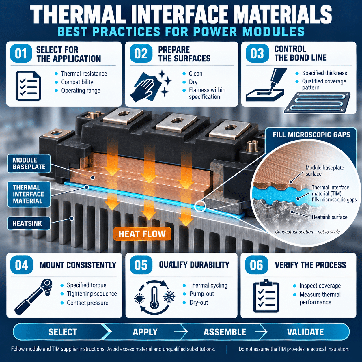
Efficient thermal management is essential to the performance and reliability of IGBT and SiC power modules. Semiconductor losses become heat, and that heat must move from the chips through the module, across the mounting interface and into the cooling system.
Even a well-designed heat sink cannot perform effectively if the interface between the module baseplate and cooling surface is poorly prepared. Microscopic gaps, excessive thermal compound, uneven mounting pressure or an unsuitable material can increase thermal resistance and raise semiconductor junction temperature.
A thermal interface material, or TIM, fills the small air gaps between mating surfaces. Selecting and applying it correctly can improve heat transfer, reduce temperature variation and support long-term module reliability.
Understand the purpose of a TIM
The baseplate of a power module and the surface of a heat sink may look smooth, but neither is perfectly flat at the microscopic level. When the two surfaces are placed together, only their highest points make direct contact. The remaining spaces contain air.
Air has low thermal conductivity, so these gaps create resistance to heat flow. A TIM displaces the air and fills the surface irregularities with a more thermally conductive material.
The TIM is not intended to create a thick thermal layer or compensate for a badly machined heat sink. Its function is to form the thinnest practical continuous interface between two surfaces that already meet the required flatness and roughness specifications.
Consider the complete thermal path
Heat must pass through several layers before reaching the surrounding environment:
- Semiconductor junction to module case
- Module case to heat sink
- Heat sink through the cooling medium
- Cooling medium to the surrounding environment or secondary cooling loop
The total thermal resistance can be represented as:
Rth,total = Rth,j-c + Rth,c-s + Rth,s-a
where:
- Rth,j-c is the junction-to-case thermal resistance
- Rth,c-s is the case-to-heat-sink contact resistance
- Rth,s-a is the heat-sink-to-ambient thermal resistance
The TIM primarily affects the case-to-heat-sink portion. A poor interface can undermine an otherwise capable module and cooling system.
Thermal design should use the module manufacturer’s stated reference points, conditions and transient thermal data. Thermal resistance values are not always directly comparable between different module families.
Choose the appropriate type of TIM
Several types of thermal interface materials are available. Each has benefits and limitations.
Thermal grease
Thermal grease is widely used with power modules because it can conform to small surface irregularities and produce low contact resistance when applied correctly.
Advantages include:
- Good surface wetting
- Low bond-line thickness
- Strong thermal performance
- Compatibility with stencil application
- No separate curing step for many products
Potential limitations include:
- Process variability
- Pump-out during thermal cycling
- Dry-out or separation over time
- Contamination during handling
- Difficulty controlling thickness without a defined process
Thermal grease should be selected and qualified for the module, cooling surface, temperature range and expected life.
Phase-change materials
A phase-change TIM is solid or semisolid at lower temperatures and softens when heated. During initial operation, it flows into surface irregularities and forms the thermal interface.
Potential advantages include:
- Controlled factory application
- Cleaner handling
- Repeatable coverage
- Reduced migration during shipping
- Simplified assembly
The installation process may require a defined initial heating cycle or operating period before final thermal performance is achieved. The selected material must reach its transition temperature under the intended conditions.
Fuji Electric has developed power modules with pre-applied phase-change TIM for applicable module families. When a module includes factory-applied TIM, follow the mounting instructions for that specific product and do not add a second interface material unless explicitly directed.
Thermal pads and films
Pads and films can provide clean, repeatable assembly. Some also provide electrical isolation.
Their disadvantages can include:
- Greater bond-line thickness
- Higher contact resistance
- Limited ability to fill large surface variations
- Compression-set behavior
- Sensitivity to mounting pressure
Do not substitute a pad for grease solely because it is easier to install. Verify the thermal impedance at the intended pressure and thickness.
Gap fillers
Gap fillers are designed for larger, less controlled spaces. They are generally not a direct substitute for the thin interface used beneath a conventional power-module baseplate.
If a design requires a thick gap-filling layer beneath the module, review the mechanical stack and heat-sink flatness before proceeding.
Do not select by thermal conductivity alone
A high thermal-conductivity value does not guarantee a low-resistance interface.
The actual result depends on:
- Bond-line thickness
- Contact pressure
- Surface flatness
- Surface roughness
- Material viscosity
- Wetting behavior
- Filler-particle size
- Pump-out resistance
- Long-term stability
- Application method
The simplified resistance of a uniform material layer is:
Rth,total = t / (kA)
where:
- t is material thickness
- k is thermal conductivity
- A is contact area
A thinner layer can outperform a thicker layer with a higher published conductivity. Contact resistance at the two surfaces also contributes to actual performance.
Evaluate the material in the intended assembly, not only from its data sheet.
Follow the module-specific mounting instructions
Power modules differ in baseplate geometry, mounting-hole pattern, allowable torque and recommended TIM pattern.
Before designing the application process, obtain the current mounting instructions for the exact module and package.
Confirm:
- Recommended TIM type
- Required thermal conductivity
- Target thickness
- Stencil pattern
- Mounting-surface requirements
- Fastener size
- Washer requirements
- Tightening torque
- Tightening sequence
- Number of tightening stages
- Post-installation inspection method
Fuji Electric provides package-specific mounting instructions for its IGBT, intelligent power module and SiC product families. These instructions should take precedence over general practices.
For several Fuji Electric industrial power-module packages, published guidance uses a thermal-grease thickness near 100 micrometers, often with a tolerance of approximately plus or minus 30 micrometers. That figure should not be applied automatically to every package or TIM. Always confirm the current value for the selected module.
Prepare the heat-sink surface correctly
The TIM cannot compensate for an unsuitable cooling surface.
Inspect the module mounting area for:
- Flatness
- Surface roughness
- Burrs
- Scratches
- Dents
- Oxidation
- Embedded particles
- Contamination
- Raised material around threaded holes
Fuji Electric mounting guidance for several module families uses a reference flatness of 50 micrometers or less over 100 millimeters and a surface roughness of 10 micrometers or less. Requirements can vary, so verify the specifications for the selected package.
Poor flatness can create two problems:
- Increased contact thermal resistance
- Mechanical stress inside the module
If the cooling surface is concave, portions of the module may not contact the heat sink properly. If it is convex or locally raised, tightening can distort the baseplate and increase stress on internal ceramic substrates.
Check flatness across the complete mounting area, including the locations around fasteners.
Clean both mating surfaces
Contamination can prevent proper wetting and create local thermal barriers.
Before applying TIM:
- Inspect the heat sink and module baseplate.
- Remove dust, oil, fingerprints and machining residue.
- Use a cleaning method compatible with both surfaces.
- Allow the surfaces to dry completely.
- Prevent new contamination before assembly.
Do not use abrasives on the module baseplate unless specifically approved. Abrasion can change flatness, damage plating or create particles.
Avoid touching cleaned surfaces with bare hands. Gloves should be clean and free from powder or release agents.
If a module has pre-applied TIM, do not clean, smear or touch the material. Protect it from dust and mechanical damage until installation.
Control the bond-line thickness
More TIM is not necessarily better.
An excessively thick layer increases thermal resistance because heat must travel through more interface material. Excess material can also accumulate near mounting holes and act as a spacer, preventing the module from seating correctly.
Too little material can leave dry regions or air pockets.
The goal is a continuous, uniform layer that fills surface irregularities without unnecessarily separating the module from the heat sink.
For thermal grease, the required mass can be estimated from:
m = A * t * ρ
where:
- m is grease mass
- A is baseplate area
- t is target thickness
ρis grease density
Use consistent units when applying the formula. The calculated mass provides a starting point, but the process must still be validated through inspection and thermal testing.
Use a stencil for repeatable application
Several application methods are possible:
- Stencil printing
- Screen printing
- Roller coating
- Automated dispensing
- Manual spreading
For production assembly, a stencil is often the most repeatable method. It controls the location and amount of material and reduces operator dependence.
A good stencil process should define:
- Stencil thickness
- Aperture pattern
- Aperture dimensions
- Material volume
- Squeegee material
- Squeegee angle
- Application pressure
- Application speed
- Stencil cleaning interval
- Acceptable coverage criteria
The best pattern may not be a solid sheet of grease. A designed array of openings can help the material spread evenly as the module is tightened.
Fuji Electric can provide recommended stencil patterns for applicable module packages. Using the package-specific pattern helps avoid excess material around mounting holes and supports more uniform coverage.
Avoid trapped air
Air pockets increase local thermal resistance and can create hot spots.
To reduce trapped air:
- Apply the correct amount of material.
- Use the recommended stencil pattern.
- Lower the module onto the heat sink evenly.
- Avoid sliding the module after contact.
- Follow the specified tightening sequence.
- Apply torque in stages.
- Do not introduce folds or wrinkles in pads and films.
Large manual deposits or random dots of grease may trap air if the material cannot spread predictably. Use a validated pattern rather than relying on visual judgment.
Apply mounting pressure evenly
The TIM application and mechanical mounting process must be designed together.
Insufficient clamping force can leave a thick bond line and incomplete contact. Excessive force can damage the module case, baseplate, internal ceramic or mounting hardware.
Use:
- Specified fastener type
- Specified washers
- Clean threads
- Correct thread engagement
- Calibrated torque tools
- Recommended tightening sequence
- Recommended number of tightening stages
A common process uses an initial low-torque pass followed by a final pass at the specified torque. The exact sequence depends on the package.
For modules with several mounting points, use the manufacturer’s pattern. Tightening one corner fully before engaging the remaining fasteners can twist the module and produce uneven pressure.
Do not use an impact driver for final tightening. A controlled torque tool provides better consistency and reduces the chance of damage.
Do not improvise fastener torque
Torque that is too low can allow:
- Increased contact resistance
- Module movement
- Thermal cycling fatigue
- Loss of interface contact
- Uneven temperature distribution
Torque that is too high can cause:
- Cracked module housings
- Baseplate deformation
- Damage to internal ceramic
- Stripped threads
- Excessive squeeze-out
Do not infer mounting torque from fastener size alone. The module manufacturer’s value accounts for package construction and allowable stress.
A torque specification should also define whether the threads are dry or lubricated. Lubrication changes the clamping force produced by a given torque.
Do not assume the TIM provides electrical insulation
Many power modules include internal electrical isolation between the semiconductor circuit and baseplate. Others have different construction.
Thermal grease is not necessarily an electrical insulator, even if its data sheet reports high volume resistivity. A thin grease layer should not be treated as a safety insulation barrier unless the complete assembly has been designed and certified for that purpose.
If additional electrical isolation is required, specify a suitable insulating interface and include its thermal resistance in the design.
Verify:
- Module isolation structure
- Heat-sink electrical potential
- Required dielectric strength
- Creepage and clearance
- Insulating pad or substrate rating
- Partial-discharge requirements
- Grounding and bonding
Do not add an insulating pad beneath a module without recalculating junction temperature.
Consider pump-out and dry-out
Thermal cycling repeatedly expands and contracts the module, heat sink and TIM. Over time, this movement can push low-viscosity material away from high-pressure regions.
Pump-out can cause:
- Reduced coverage
- Dry areas
- Grease accumulation at the perimeter
- Increased contact thermal resistance
- Higher junction temperature
Dry-out occurs when volatile components evaporate or the material changes consistency. This can reduce its ability to maintain surface contact.
Material qualification should reflect:
- Maximum and minimum temperature
- Temperature-cycle amplitude
- Number of cycles
- Dwell time
- Vibration
- Orientation
- Mounting pressure
- Expected service life
A grease that performs well in an initial room-temperature test may not remain stable after years of cycling.
Account for material compatibility
Check compatibility among the TIM, module baseplate, heat-sink coating, gasket materials and cleaning agents.
Potential problems include:
- Corrosion
- Silicone migration
- Swelling
- Loss of adhesion
- Surface staining
- Chemical attack
- Contamination of nearby contacts
- Outgassing
Silicone-based materials can be restricted in some applications because migrating compounds may affect relays, contacts, sensors or optical surfaces.
If the converter serves transportation, medical, aerospace or sealed equipment applications, review outgassing and contamination requirements carefully.
Manage storage and shelf life
TIM properties can change during storage.
Control:
- Storage temperature
- Humidity
- Container sealing
- Shelf life
- Lot traceability
- Mixing requirements
- Settling
- Exposure to air
- Contamination
Record the material lot used for each production batch.
If the material requires mixing, define the method and duration. Avoid introducing air during mixing.
Pre-applied TIM modules should remain in their protective packaging until assembly. Do not stack or place objects against the coated surface.
Validate coverage with a witness test
A practical way to evaluate grease spreading is to assemble a representative module and then remove it for inspection.
A good witness pattern should show:
- Coverage across the intended baseplate area
- Minimal dry regions
- No large trapped bubbles
- Controlled squeeze-out
- No excessive buildup around mounting holes
- Evidence of even pressure
The witness test is destructive to that interface. Once removed, the module and heat sink should be cleaned and prepared with fresh TIM before final installation.
Do not remount a module using the disturbed grease layer unless the manufacturer’s procedure explicitly allows it.
Validate thermal performance
Visual coverage is necessary but not sufficient. Confirm the interface with thermal measurements.
Possible methods include:
- Case-temperature measurement
- Heat-sink temperature measurement
- Built-in chip temperature estimation
- Calibrated temperature-sensitive electrical parameters
- Thermocouples
- Infrared imaging, with suitable emissivity preparation
- Coolant inlet and outlet measurements
- Calorimetric testing
Test under representative worst-case conditions:
- Maximum semiconductor loss
- Maximum coolant or ambient temperature
- Minimum coolant flow
- Maximum allowed switching frequency
- Expected installation orientation
- Adjacent module heating
- Fan or pump tolerance
Use the resulting data to verify junction temperature with the appropriate thermal model.
Infrared imaging can identify uneven heating, but it cannot see through an opaque module case or metal baseplate. Interpret surface temperatures together with electrical loss and thermal-resistance data.
Include transient conditions
Steady-state testing alone may not capture the highest junction temperature.
Evaluate:
- Short overloads
- Acceleration
- Regenerative operation
- Pulse loads
- Short duty cycles
- Fault ride-through
- Repetitive peak current
- Startup before coolant reaches normal flow
Use the module’s transient thermal-impedance data to estimate junction-temperature excursions.
The TIM affects how heat spreads into the heat sink over time. Its influence may become more significant as a pulse becomes longer and heat reaches the mounting interface.
Pay special attention to SiC modules
SiC devices can provide lower switching loss and higher power density, but compact designs may create high local heat flux.
This makes interface quality especially important.
A SiC design may require:
- Tighter control of bond-line thickness
- Lower-inductance mechanical integration
- Higher coolant performance
- Careful gate-drive and thermal co-design
- Accurate temperature estimation
- More demanding cycling qualification
Do not assume that a TIM qualified for an older silicon IGBT assembly will automatically meet the needs of a higher-density SiC design.
The same general type of thermal grease may be usable with both technologies, but the material and application process should be validated for the specific module, loss density and temperature profile.
Control the production process
TIM application should be treated as a controlled manufacturing process.
Document:
- Approved material and alternates
- Lot and expiration checks
- Surface-cleaning method
- Target material mass
- Stencil identification
- Application parameters
- Coverage inspection
- Fastener sequence
- Initial and final torque
- Torque-tool calibration
- Cure or initial heating requirements
- Rework procedure
- Acceptance criteria
Train operators to recognize:
- Incomplete prints
- Excess material
- Contamination
- Damaged stencils
- Air bubbles
- Expired grease
- Incorrect fasteners
- Uneven seating
Statistical process control can help identify gradual changes in dispensed mass, stencil wear or torque consistency.
Establish a rework procedure
Removing a mounted module disturbs the thermal interface.
For rework:
- Follow the equipment’s electrical safety procedure.
- Remove the module using the specified loosening sequence.
- Prevent mechanical damage to the baseplate and pins.
- Remove the old TIM completely.
- Use approved cleaning materials.
- Inspect both mating surfaces.
- Apply new TIM.
- Remount using the full controlled process.
- Repeat required electrical and thermal tests.
Do not mix old and new thermal grease. Do not apply fresh material over a contaminated surface.
If a pre-applied phase-change layer is damaged or has already been through its activation cycle, consult the module-specific instructions before reuse.
Common TIM mistakes
Applying too much material
A thick layer increases thermal resistance and may prevent the module from seating correctly.
Applying too little material
Insufficient material leaves air gaps and local hot spots.
Using an unqualified substitute
Materials with similar thermal-conductivity values can behave very differently under pressure and temperature cycling.
Ignoring heat-sink flatness
TIM cannot correct a warped or damaged cooling surface.
Tightening one fastener fully at a time
Uneven tightening can distort the module and create nonuniform contact.
Treating torque as approximate
Incorrect torque affects both thermal performance and mechanical reliability.
Reusing disturbed TIM
Removing the module can introduce contamination and air into the interface.
Assuming pre-applied TIM requires additional grease
Adding grease to a factory-applied interface can increase thickness and degrade performance.
Using TIM as electrical insulation without verification
The thermal interface may not provide the required dielectric protection.
Skipping thermal-cycle testing
Initial performance does not prove long-term stability.
TIM design and assembly checklist
Before releasing a power-module assembly, confirm:
- Is the TIM approved for the exact module and heat-sink combination?
- Does the material meet the required operating-temperature range?
- Has pump-out and dry-out performance been evaluated?
- Does the heat sink meet flatness and roughness requirements?
- Are both mating surfaces clean and undamaged?
- Is the target bond-line thickness defined?
- Is the required material mass documented?
- Is a package-specific stencil pattern available?
- Has the application process been validated?
- Does the witness pattern show complete coverage?
- Are the fastener type and washers specified?
- Is the tightening sequence documented?
- Is torque applied in the required stages?
- Are torque tools calibrated?
- Is electrical isolation provided independently where required?
- Have steady-state and transient thermal conditions been tested?
- Has the interface been evaluated after thermal cycling?
- Are storage, shelf-life and lot-traceability controls in place?
- Is there a documented rework procedure?
- Are current module-specific mounting instructions controlled in production?
Treat the thermal interface as part of the power module design
The thermal interface is a small part of a converter’s physical construction, but it can have a major effect on junction temperature, power capability and reliability.
The best results come from combining a qualified TIM with a flat, clean heat sink, controlled bond-line thickness, uniform application and the correct mounting sequence. Material selection, mechanical design and manufacturing controls must work together.
Fuji Electric provides package-specific mounting instructions and application guidance for its IGBT, intelligent power module and SiC product families. Following the instructions for the exact module, rather than applying one generic process to every package, helps ensure consistent thermal performance throughout the converter’s service life.