
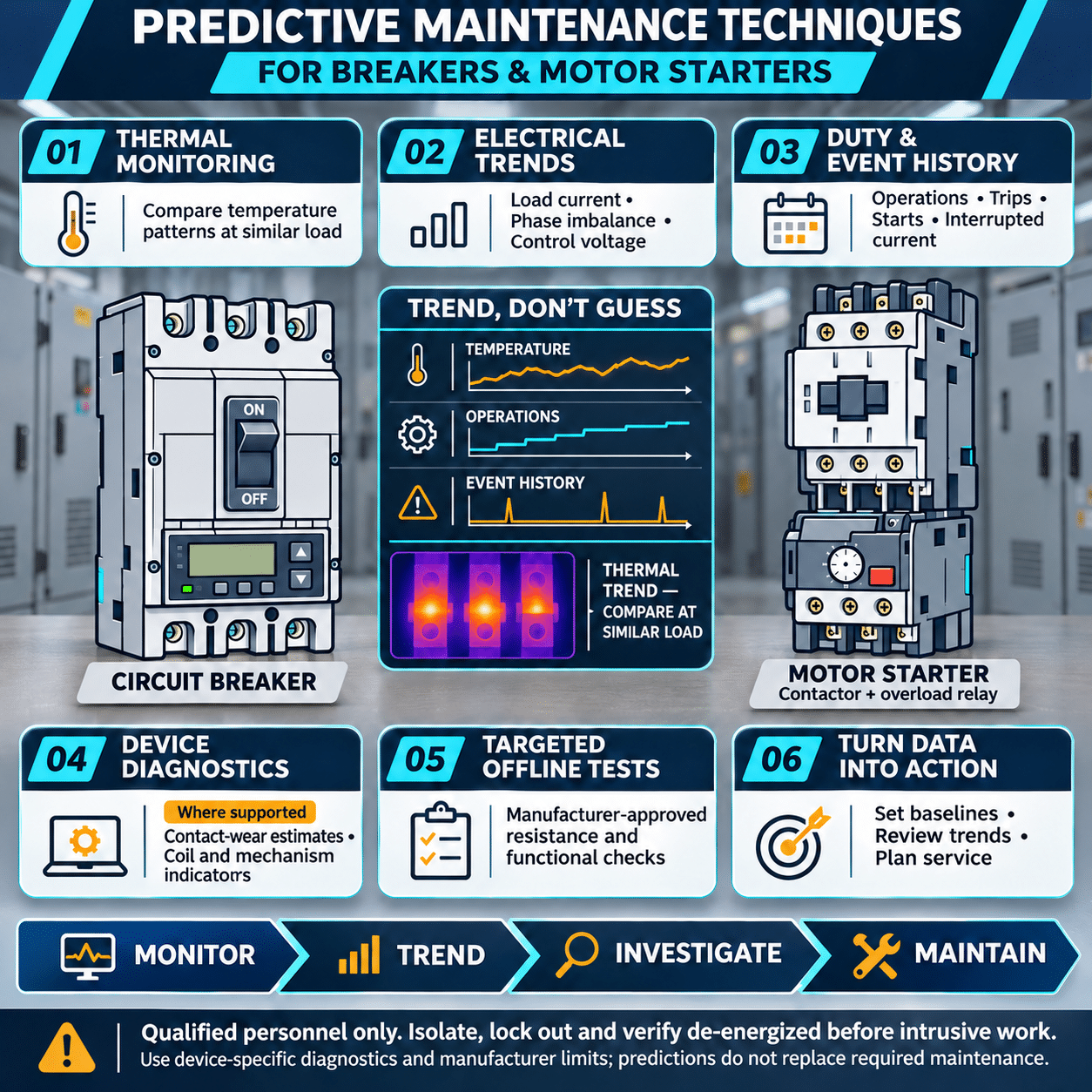
Circuit breakers and motor starters operate quietly in the background of industrial and commercial electrical systems. A breaker may remain closed for years before it is called upon to interrupt a fault. A motor starter may open and close thousands of times while carrying high inrush current and controlling a demanding mechanical load.
Both devices can appear normal from the outside while internal deterioration is developing. Loose connections, contact erosion, dried lubricant, weakened springs, coil damage, contamination, and excessive heat may eventually cause nuisance trips, failure to start, failure to open, or complete equipment damage.
Predictive maintenance helps identify these conditions before they become functional failures. Instead of replacing equipment solely according to a calendar, maintenance teams collect condition data, compare it with previous results, and intervene when evidence shows that deterioration is progressing.
An effective program combines predictive techniques with scheduled inspection, testing, and manufacturer recommendations. Predictive monitoring does not eliminate preventive maintenance, but it can make maintenance decisions more focused and defensible.
Why Breaker and Starter Failures Matter
A failed breaker may:
- Trip unexpectedly and interrupt production
- Refuse to close after a shutdown
- Fail to clear a fault within the required time
- Overheat at a damaged connection
- Allow protective coordination to be lost
- Increase the energy released during an electrical fault
- Create a fire, shock, or arc-flash hazard
A failed motor starter may:
- Prevent a motor from starting
- Drop out during operation
- Allow single-phasing
- Overheat the motor
- Weld its contacts closed
- Chatter and damage contact surfaces
- Cause repeated process interruptions
- Fail to trip during an overload
These failures can affect more than the individual circuit. A single unreliable starter may stop a cooling-water pump, exhaust fan, conveyor, compressor, or production machine. A breaker that does not operate as intended can affect the safety and coordination of the entire distribution system.
Predictive, Preventive, and Corrective Maintenance
The three maintenance approaches serve different purposes.
Preventive maintenance is performed at planned intervals. Examples include cleaning equipment, exercising breaker mechanisms, tightening connections according to approved procedures, and replacing components after a specified number of operations.
Predictive maintenance evaluates equipment condition using measurements and trends. Examples include thermography, contact-resistance testing, coil-current analysis, and operation-count monitoring.
Corrective maintenance occurs after a problem is found or a failure occurs. It may include replacing a burned contactor, repairing a breaker mechanism, or correcting a loose termination.
The strongest electrical maintenance programs use all three. Predictive data helps determine where preventive work is most urgent, while corrective procedures address defects discovered during inspection and testing.
Use the Potential-Failure-to-Functional-Failure Curve
Equipment deterioration often begins before the device can no longer perform its intended function.
The interval between the first detectable sign of deterioration and functional failure is commonly described by the potential-failure-to-functional-failure curve, or P-F curve.
For example:
- A connection gradually loosens.
- Contact resistance begins to rise.
- A thermal scan detects an abnormal temperature difference.
- Discoloration or insulation damage becomes visible.
- The connection overheats and fails.
The goal is to detect the problem during the early stages, when maintenance can be planned rather than performed during an emergency.
Different techniques detect different stages of deterioration. Online temperature monitoring may identify a developing resistive connection early, while visual inspection may not reveal the problem until significant heating has occurred.
Establish a Condition Baseline
Predictive maintenance is based on comparison. A single reading has limited value unless it can be compared with a baseline, similar equipment, or a recognized acceptance criterion.
Record baseline data when equipment is:
- Newly installed
- Commissioned
- Returned from overhaul
- Replaced
- Verified to be operating correctly
Useful baseline information includes:
- Equipment manufacturer and model
- Serial number
- Frame and trip ratings
- Protective settings
- Motor nameplate data
- Starter utilization category
- Contactor and overload-relay ratings
- Installation date
- Number of mechanical and electrical operations
- Load current by phase
- Connection temperatures
- Contact resistance
- Insulation resistance
- Breaker trip times
- Coil voltage and current
- Ambient temperature
- Photographs
- Previous maintenance findings
Test conditions should also be documented. Measurements taken at different loads, temperatures, or instrument settings may not be directly comparable.
Start With a Criticality Assessment
Not every breaker and starter requires the same level of monitoring.
Assign higher priority to equipment that:
- Supports a life-safety system
- Has no installed redundancy
- Controls a critical production process
- Has a history of failure
- Operates frequently
- Interrupts high fault current
- Is exposed to heat, moisture, dust, vibration, or corrosive material
- Has limited spare-part availability
- Would require a long outage to replace
- Supplies many downstream loads
- Operates near its continuous-current rating
A lightly loaded branch breaker serving a noncritical receptacle circuit does not necessarily require the same testing program as a main power breaker or a starter controlling a critical cooling pump.
Criticality helps determine inspection frequency, testing depth, spare-parts strategy, and replacement planning.
Infrared Thermography
Infrared thermography is one of the most useful online techniques for breakers and motor starters. It can identify abnormal heating without interrupting operation.
Thermal inspections may reveal:
- Loose line or load connections
- High-resistance contacts
- Overloaded conductors
- Phase imbalance
- Damaged fuse clips
- Failing contactor poles
- Undersized conductors
- Poor bus connections
- Excessive coil heating
- Ventilation problems
- Abnormally hot overload-relay connections
Compare Similar Components
Temperature should not be evaluated in isolation. Compare:
- One phase with the other phases
- Similar starters carrying similar loads
- Incoming and outgoing terminals
- Present readings with previous surveys
- Measured temperature with ambient temperature
- Temperature with actual circuit load
One phase that is significantly hotter than the others may indicate a loose termination, contact wear, or phase-current imbalance.
A component that is uniformly hot may be heavily loaded rather than defective. Load current should be recorded during the scan so the thermal result can be interpreted correctly.
Inspect Under Meaningful Load
A thermal scan performed on lightly loaded equipment may not reveal a resistive connection. Whenever practical, inspect the device while it carries a representative, stable load.
The report should include:
- Equipment identification
- Thermal and visual images
- Load current
- Ambient temperature
- Emissivity assumptions
- Temperature differences
- Apparent severity
- Recommended follow-up
- Date for corrective action
Thermography identifies heat, but it does not determine the exact root cause. An abnormal result should lead to an appropriate de-energized inspection or electrical test.
Continuous Temperature Monitoring
Periodic thermography provides a snapshot. Permanently installed temperature sensors can provide continuous information for critical equipment.
Sensors may be applied near:
- Breaker line and load terminals
- Bus connections
- Drawout stabs
- Contactor terminals
- Cable lugs
- Motor-control-center connections
Continuous monitoring is useful when:
- Equipment cannot be inspected easily while energized
- Loads change frequently
- The process operates continuously
- Electrical rooms are unattended
- An outage would be costly
- The interval between a detectable defect and failure may be short
Alarm thresholds should account for ambient temperature, load, phase comparison, and rate of change. A rising temperature trend may be more meaningful than a single absolute value.
Visual and Mechanical Inspection
Visual inspection remains essential because many defects are not primarily thermal.
Look for:
- Discoloration
- Cracked insulation
- Melted material
- Corrosion
- Moisture
- Dust buildup
- Carbon deposits
- Loose or missing hardware
- Damaged arc chutes
- Worn moving parts
- Broken barriers
- Frayed control wiring
- Evidence of arcing
- Abnormal odor
- Pest contamination
- Water tracks
- Improper modifications
For breakers, check whether the operating handle, charging mechanism, position indicator, and trip indication function normally.
For starters, inspect the armature, coil, shading ring where applicable, contact carrier, auxiliary contacts, overload relay, and mechanical interlocks.
The presence of dust is not merely cosmetic. Conductive or moisture-absorbing contamination can reduce insulation performance, interfere with movement, and contribute to tracking.
Mechanical Operation and Exercise
A breaker that remains closed for years may develop dried lubricant, corrosion, or mechanism stiffness. Periodic operation can help reveal problems that are not visible during normal energized service.
Depending on the equipment type and manufacturer instructions, maintenance may include:
- Opening and closing the breaker
- Charging and releasing stored-energy mechanisms
- Testing the trip-free function
- Inspecting drawout movement
- Checking interlocks
- Verifying mechanical indicators
- Exercising manual motor starters
- Checking contactor movement
- Confirming that reversing or transfer interlocks prevent simultaneous closure
Operation should feel consistent and should not require unusual force. Slow, incomplete, or erratic movement can indicate contamination, wear, misalignment, or degraded lubrication.
Do not apply an unapproved lubricant. The wrong material may attract dust, damage plastics, change mechanism timing, or become ineffective at operating temperature.
Contact-Resistance Testing
Current-carrying contacts and connections should have very low resistance. Wear, oxidation, contamination, loss of contact pressure, or poor alignment can increase resistance and create heat.
A low-resistance ohmmeter can be used to measure the resistance of:
- Breaker poles
- Drawout connections
- Bus joints
- Contactor poles
- Disconnect contacts
- Cable terminations
The test should be performed with the equipment de-energized, isolated, and prepared according to the manufacturer’s instructions.
Compare:
- Phase-to-phase values
- Current results with baseline data
- Results before and after maintenance
- Values with manufacturer limits where available
A large difference among phases can indicate a problem even if no universal resistance limit is available.
Connections should not automatically be tightened simply because a resistance reading is elevated. The cause may be internal contact wear, damaged plating, misalignment, or a defective conductor termination. Repeated tightening can damage hardware or exceed the approved torque.
Insulation-Resistance Testing
Insulation-resistance testing helps evaluate contamination, moisture, insulation damage, and deterioration between conductors and ground.
It may be applied to:
- Breaker poles
- Motor-starter power circuits
- Control wiring
- Disconnects
- Motor feeders
- Bus assemblies
Sensitive electronics, surge-protection devices, electronic trip units, solid-state overload relays, and connected equipment may need to be isolated before the test voltage is applied.
Results depend on temperature, humidity, test duration, and equipment configuration. Trending measurements under comparable conditions is usually more useful than relying on a single reading.
A low result should lead to investigation for:
- Moisture
- Dust
- Damaged insulation
- Carbon tracking
- Contaminated arc chutes
- Deteriorated wiring
- Connected loads affecting the measurement
Testing should follow the manufacturer’s instructions and the facility’s electrical maintenance procedures.
Breaker Trip Testing
A breaker’s most important function is to interrupt current when required. Mechanical appearance alone cannot verify protective performance.
Testing methods may include:
Mechanical Trip Test
A manual push-to-trip mechanism, where provided, confirms basic mechanical release. It does not verify the accuracy of the complete trip system.
Secondary-Injection Testing
Secondary injection applies a simulated signal to an electronic trip unit. It can verify trip-unit logic, settings, timing, indications, and outputs without passing high current through the breaker’s primary path.
This method does not test every current-carrying component of the primary circuit.
Primary-Injection Testing
Primary injection passes controlled current through the breaker poles. It can evaluate the current sensors, trip unit, wiring, trip actuator, and mechanical opening sequence together.
Depending on the breaker and test equipment, primary injection can verify long-time, short-time, instantaneous, or ground-fault functions.
Test results should be compared with:
- The trip-unit settings
- Published time-current curves
- Manufacturer tolerances
- Previous test results
- The protective-coordination study
If protective settings have changed since the coordination study, the effect on downstream selectivity and incident energy should be evaluated.
Breaker Timing and Motion Analysis
For larger power breakers, timing and motion tests can reveal deterioration in the operating mechanism.
Measurements may include:
- Opening time
- Closing time
- Pole simultaneity
- Contact travel
- Contact velocity
- Contact bounce
- Stored-energy mechanism performance
- Trip and close coil current
Changes over time may indicate:
- Increased friction
- Weak springs
- Binding linkages
- Coil deterioration
- Mechanism misalignment
- Worn latches
- Incorrect lubrication
- Control-voltage problems
Timing and motion testing requires equipment-specific knowledge. Procedures and acceptance criteria should come from the breaker manufacturer or a qualified service provider.
Monitor Breaker Operations and Fault History
Operation counts provide useful life-cycle information. The effect of an operation depends on what the breaker interrupted.
Opening under no load causes less electrical wear than interrupting a high fault current. Maintenance records should distinguish among:
- Manual operations
- Normal load switching
- Overload trips
- Short-circuit interruptions
- Ground-fault operations
- Test operations
- Failed closing attempts
After a major fault interruption, the breaker should be inspected or evaluated according to the manufacturer’s instructions. A breaker may appear to reset normally while its contacts or arc-control components have sustained significant stress.
Electronic trip units and monitoring systems may provide:
- Trip cause
- Phase current
- Ground current
- Peak fault current
- Timestamp
- Protective element that operated
- Number of trips
- Load history
- Pre-alarm conditions
This information can help distinguish a breaker problem from a genuine system fault.
Motor Starter Contact Monitoring
A magnetic contactor opens and closes a motor circuit repeatedly. Each operation can produce an arc that gradually erodes the contact material.
Signs of contact deterioration include:
- Increasing voltage drop
- Rising temperature
- Phase-to-phase imbalance
- Visible pitting
- Material transfer
- Reduced contact thickness
- Welding
- Chattering
- Unusual sound
- Intermittent motor operation
Contact condition should be evaluated according to the manufacturer’s inspection and replacement criteria. Contacts should not be filed or dressed unless the manufacturer specifically permits it. Removing material can alter the contact profile, plating, pressure, and electrical life.
For critical starters, operation counts can be compared with the contactor’s rated mechanical and electrical endurance under the applicable utilization category.
The electrical life of a contactor depends on the load. Frequently plugging, jogging, reversing, or switching a high-inrush motor can produce more contact wear than ordinary starting and stopping.
Coil-Current and Coil-Voltage Analysis
The contactor coil creates the magnetic force that closes and holds the main contacts. Problems in the coil circuit can lead to delayed pickup, chatter, overheating, or failure to close.
Measure:
- Voltage during pickup
- Holding voltage
- Pickup current
- Holding current
- Voltage drop in control wiring
- Dropout behavior
- Coil temperature where appropriate
Low control voltage may prevent the armature from closing completely. The resulting air gap can cause high coil current, vibration, and rapid overheating.
Potential causes include:
- Undersized control transformer
- Excessive control-wire length
- Loose connections
- Damaged auxiliary contacts
- Incorrect coil voltage
- Power-supply sag during motor starting
- Contaminated or mechanically obstructed armature
- Failing interposing relay
Current-waveform analysis can provide additional information in advanced applications. Changes in the coil-current signature may indicate altered armature travel, binding, or delayed closure.
Listen for Contactor Chatter
An abnormal buzzing or chattering contactor should be investigated promptly.
Possible causes include:
- Low coil voltage
- Incorrect supply frequency
- Contaminated magnetic surfaces
- Damaged shading coil
- Loose laminations
- Mechanical obstruction
- Worn armature
- Unstable PLC or relay output
- Rapidly changing process command
Chatter repeatedly makes and breaks contact pressure, causing arcing and accelerated wear. It can also create unreliable motor voltage and damage the connected equipment.
Sound can be included in route-based inspections. A technician familiar with the normal equipment can often identify a change before a failure occurs. Acoustic or ultrasonic instruments may support more consistent detection.
Test Overload Protection
The overload relay protects the motor against sustained overcurrent and, depending on the design, may also respond to phase loss or current imbalance.
Verify:
- Correct current setting
- Correct trip class
- Heater or sensor selection
- Ambient compensation where applicable
- Reset mode
- Phase-loss behavior
- Mechanical linkage
- Auxiliary contact operation
- Trip indication
- Communication settings for electronic relays
The overload setting should be based on the motor nameplate and applicable design requirements, not adjusted upward merely to prevent tripping.
Repeated overload trips may indicate:
- Excessive mechanical load
- Motor damage
- Low voltage
- Phase imbalance
- Frequent starting
- High ambient temperature
- Incorrect relay setting
- Incorrect trip class
- A failing starter contact
- Process problems
Motor current should be measured on all phases and compared with the motor’s operating condition.
Monitor Current and Voltage Imbalance
Phase imbalance can damage both starters and motors. A worn or high-resistance contactor pole may create a voltage imbalance at the motor even when the upstream supply is balanced.
Monitor:
- Line-to-line voltage at the starter input
- Line-to-line voltage at the starter output
- Current on all phases
- Voltage drop across each closed contact
- Motor load and process condition
A significant difference in voltage drop across one contactor pole points toward a contact or connection problem.
Current imbalance can also result from motor winding faults, supply problems, uneven single-phase loading elsewhere in the system, or mechanical conditions. Measurements on both sides of the starter help narrow the cause.
Use Motor Data as an Indicator of Starter Condition
A starter problem may first appear in motor operating data.
Useful indicators include:
- Starting current
- Starting time
- Running current
- Phase imbalance
- Number of starts
- Time between starts
- Overload events
- Motor temperature
- Acceleration time
- Failed-start count
A motor that takes longer to accelerate may keep the contactor and overload relay under high-current stress for longer than expected. The root cause could be mechanical binding, low voltage, increased process load, or motor deterioration.
Tracking starts per hour is particularly important for high-cycle applications. Frequent starting can exceed the thermal capability of the motor, contactor, overload relay, or control transformer.
Apply Environmental Monitoring
Equipment condition is strongly influenced by its environment.
Monitor or inspect for:
- Ambient temperature
- Humidity
- Condensation
- Dust
- Oil mist
- Chemical vapors
- Salt contamination
- Vibration
- Insects and rodents
- Water entry
- Corrosive atmosphere
Motor control centers near process equipment may be exposed to contaminants even when they are installed indoors.
Heaters, ventilation systems, filters, gaskets, and enclosure seals should be maintained along with the electrical devices. Replacing a failed contactor without correcting the moisture or contamination that damaged it will not provide a lasting solution.
Build Useful Trend Data
A predictive program should convert individual measurements into trends.
For each asset, track values such as:
- Maximum terminal temperature
- Phase temperature difference
- Contact resistance
- Insulation resistance
- Breaker trip time
- Opening and closing time
- Coil pickup current
- Coil holding current
- Contactor voltage drop
- Number of operations
- Number and cause of trips
- Motor starting time
- Phase-current imbalance
Use consistent equipment names and test methods. If one technician records a breaker as “MCC Main” and another calls it “Breaker 1,” long-term comparison becomes difficult.
Photographs and thermal images should be linked to the correct asset record. Test instruments should be identified, and calibration status should be maintained.
Create Action Thresholds
Data is useful only when it leads to decisions.
A practical condition scale may classify equipment as:
Normal
Readings are stable, and no abnormal condition is present.
Monitor
A small change has appeared, but immediate intervention is not required. Increase inspection frequency.
Plan repair
Deterioration is confirmed. Schedule an outage, obtain parts, and prepare a repair procedure.
Urgent
The condition presents a high likelihood of failure or unacceptable safety risk. Escalate according to the facility’s electrical safety and operational procedures.
Thresholds should consider:
- Manufacturer criteria
- Applicable standards
- Baseline values
- Rate of change
- Load
- Criticality
- Redundancy
- Consequence of failure
- Qualified engineering judgment
A rapidly worsening trend may require more urgent action than a higher but stable reading.
Keep Predictive Maintenance Safe
Many predictive techniques are performed on energized equipment, but energized access presents electrical hazards.
Thermography, online measurements, and sensor installation should follow the facility’s electrical safety program and applicable requirements for:
- Shock protection
- Arc-flash risk assessment
- Qualified personnel
- Energized work justification
- Approach boundaries
- Personal protective equipment
- Test-instrument ratings
- Equipment labeling
- Safe work procedures
Opening an enclosure for a thermal scan may change the worker’s exposure. Infrared windows or permanently installed sensors can reduce the need to open energized equipment, but they must be properly selected and installed.
De-energized work still requires an electrically safe work condition, including identification of all sources, isolation, lockout and tagout, absence-of-voltage testing, and control of stored energy.
Know When to Repair and When to Replace
Not every breaker or starter should be repaired.
Replacement may be more appropriate when:
- The device has interrupted a major fault
- Contacts or arc chutes are severely damaged
- The mechanism operates inconsistently
- Insulation is cracked, carbonized, or tracked
- Parts are obsolete or unavailable
- Test results remain unacceptable after maintenance
- The device has exceeded its rated operations
- The equipment is approaching its recommended renewal period
- The application has changed
- The available fault current exceeds the equipment rating
- Modern diagnostics or protection would materially improve reliability
Some molded-case breakers are not intended for field repair. If an internal defect is suspected, replacement or manufacturer evaluation may be required.
Fuji Electric provides recommended renewal guidance for its equipment. Such guidance should be considered along with operating conditions, switching duty, inspection results, and the manufacturer’s specified operating life. A calendar age alone is not a guarantee of remaining performance.
Applying Predictive Maintenance to Fuji Electric Equipment
Fuji Electric’s distribution and control portfolio includes molded-case circuit breakers, earth-leakage circuit breakers, manual motor starters, magnetic contactors, thermal overload relays, and combination starter solutions.
Examples include:
- G-TWIN molded-case and earth-leakage circuit breakers
- DUO manual motor starters and combination starter arrangements
- SC Series contactors and motor starters
- SK Series compact contactors and overload relays
Maintenance procedures should be based on the exact product model. Inspection points, allowable test methods, torque values, replacement criteria, operating life, and accessory arrangements can differ by frame size and device family.
The equipment nameplate, instruction manual, test documentation, and applicable maintenance standard should be reviewed before work begins.
Predictive Maintenance Checklist
For circuit breakers, consider tracking:
- Visual condition
- Environmental condition
- Terminal temperature
- Load current by phase
- Contact resistance
- Insulation resistance
- Mechanical operation
- Trip-unit settings
- Trip time
- Ground-fault operation
- Opening and closing time
- Operation count
- Fault-interruption history
- Accessory operation
- Drawout mechanism condition
- Remaining product support
For motor starters, consider tracking:
- Visual condition
- Contactor temperature
- Motor current by phase
- Input and output voltage
- Voltage drop across each pole
- Contact condition
- Operation count
- Coil pickup voltage
- Coil current
- Abnormal sound
- Mechanical movement
- Auxiliary-contact operation
- Overload-relay setting
- Overload trip performance
- Motor starting time
- Number of starts
- Environmental contamination
Turn Measurements Into Better Maintenance Decisions
Predictive maintenance is not simply the collection of thermal images and test reports. Its value comes from detecting change, understanding what the change means, and acting before equipment loses its intended function.
For breakers, the most useful program combines load and temperature monitoring with mechanical operation, contact testing, insulation assessment, and verification of protective performance.
For motor starters, maintenance should focus on contact condition, coil behavior, phase balance, overload protection, switching frequency, and the electrical and mechanical condition of the connected motor.
When these measurements are organized by equipment criticality and reviewed as trends, maintenance teams can plan outages more effectively, replace components before they fail, and maintain greater confidence that breakers and starters will operate when required.