
Flameproof Thermal Conductivity Gas Analyzer (ZAFE)
Ideal for H2, Ar, and He measurement
- Easy-to-see LCD
- RS-232C communication (option)
- Compact, panel mount design
- Automatic calibration (option)
- Interference compensation (option)
- Concentration alarm (option)
High/low limit, high-high limit, or low-low limit - Range switching (option) by key on the front panel or by an external contact input.
- NEPSI (Exd IIC T6Gb) certified
Applications
- H2 monitoring in semiconductor manufacturing equipment, hydrogen generation equipment, calcining furnaces, and the like.
- Ar, He, CH4 measurement in gas generation plants
- He measurement in superconducting devices
- Ar measurement in air-separation plants
Principle
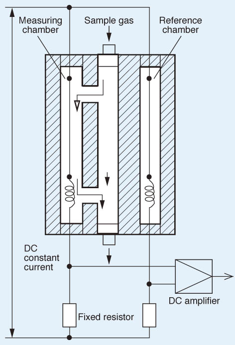 This thermal conductivity gas analyzer measures gas concentration by utilizing the difference of thermal conductivities between two gas components. In the detector, there are a reference chamber and a measuring chamber, in each of which a thin platinum wire is stretched. The reference chamber is filled with reference gas. The sample gas is flowed through the measuring chamber. Each platinum wire composes a bridge circuit in combination with an external fixed resistor, and is heated by flowing a constant current. When there is a change in the concentration of the component under measurement, the thermal conductivity of sample gas will change to affect the temperature of the platinum wire in the measuring chamber. The resulting thermal change is taken out as a change in electric resistance, according to which the concentration of measured gas is calculated.
Specifications
| Standard specifications | Principle | Thermal conductivity |
|---|---|---|
| Components | He, Ar, H2, CH4, CO2 | |
| Range | H2: 0–3 ‥‥ 100%, 100–90%, 100–80% He: 0–5 ‥‥ 100%, 100–90%, 100–80% Ar: 0–10 ‥‥ 100%, 100–90%, 100–80% CH4: 0–20 ‥‥ 100%, 100–80% |
|
| Output signal | 4–20 mA DC, 0–1 V DC, or 0–10 mV DC, non-isolated output | |
| Load resistance | ≤ 550Ω (at 4–20 mA DC output) | |
| Output resistance | 100 kΩ (at 0–1 V DC or 0–10 mV DC) | |
| Display | LCD with back light | |
| Display | 4-digit | |
| Output hold | In both manual and automatic calibrations, output value just before calibration can be held | |
| Power supply & consumption | 100–240 V AC, 50/60 Hz, approx. 50 VA | |
| Ambient temperature & humidity | -5 to 45°C, RH 90% or less (non condensation) | |
| Mounting | Wall mount | |
| Dimensions (H x W x D) | 470 × 354 × 211 mm | |
| Weight | Approx. 22 kg | |
| Enclosure | Dustproof and rainproof (IP65 equivalent) | |
| Gas inlet/outlet | Rc 1/2, NPT 1/2, or G 1/2 (as specified) | |
| Ex-proof standard | NEPSI (Exd IIC T6Gb) | |
| Performance | Repeatability | ±1%FS |
| Drift | Zero point: ≤ ±2% FS per week (H2measurement) Span point: ≤ ±2% FS per week (H2measurement) |
|
| Response speed (90% response) | Standard: ≤ 60 s (at flow rate 0.4 L/min) High speed: ≤ 10 s (at flow rate 1 L/min) allowed only for H2 measurement (reference gas N2) |
|
| Gas conditions | Temperature | 0–50°C |
| Gas flow rate | Constant at 0.4 ±0.05 L/min | |
| Dust | ≤ 100 μg/Nm3 in particle size of 0.3 μm or smaller | |
| Pressure | ≤ 10 kPa | |
| Mist, corrosive gas | Unallowable | |
| Moisture | Below saturation at 2°C | |
| Optional specifications | ||
| Relay contact output | 5 SPST relay contact outputs Relay contact capacity: 220 V AC/2A (resistive load) Isolated with relay between contacts, and between contacts and internal circuit. Max. 5 functions can be selected among those listed below. ① Zero-side solenoid valve drive output for automatic calibration ② Span-side solenoid valve drive output for automatic calibration ③ Suction pump OFF output in automatic calibration ④ Upper limit (1 point) concentration alarm output ⑤ Lower limit (1 point) concentration alarm output ⑥ Upper/lower limit (1point) concentration alarm output ⑦ Upper limit (1 point) and lower limit (1 point) concentration alarm output (Total 2 points) ⑧ 2-step upper limit (1 point at each step) concentration alarm output (Total 2 points) ⑨ 2-step lower limit (1 point at each step) concentration alarm output (Total 2 points) ⑩ Analyzer error or automatic calibration error alarm output ⑪ Calibrating status output ⑫ Range identification output (for 2 range type only) |
|
| Contact input | 3 non-voltage contact inputs ON: 0 V, OFF: 5V DC, current at ON: 5mA Isolated with photo coupler between inputs and internal circuit. Not isolated between contact inputs. The following actions are available: ① Remote holding of measured value output ② Remote range changeover (only with 2-range analyzer) ③ Remote start of automatic calibration |
|
| Interference gas measured value input | 1–5 V DC analog input for H2 analyzer interference correction Either CO2 or CH4 value measured by an external gas analyzer Adjustment at Fuji Electric factory is required. We will check the details of the gas to be measured when receiving an order. |
|
| Auto calibration | Zero and span calibrations are automatically carried out at the predetermined intervals. Externally installed solenoid valves are driven to flow calibration gas sequentially. | |
| Communication | RS-232C (9-pin D-sub output) Half duplex, asynchronous MODBUS protocol, communication speed 9600 bps Contents of communication: Reading/writing of measured concentration values and various set values, and output of device status |