
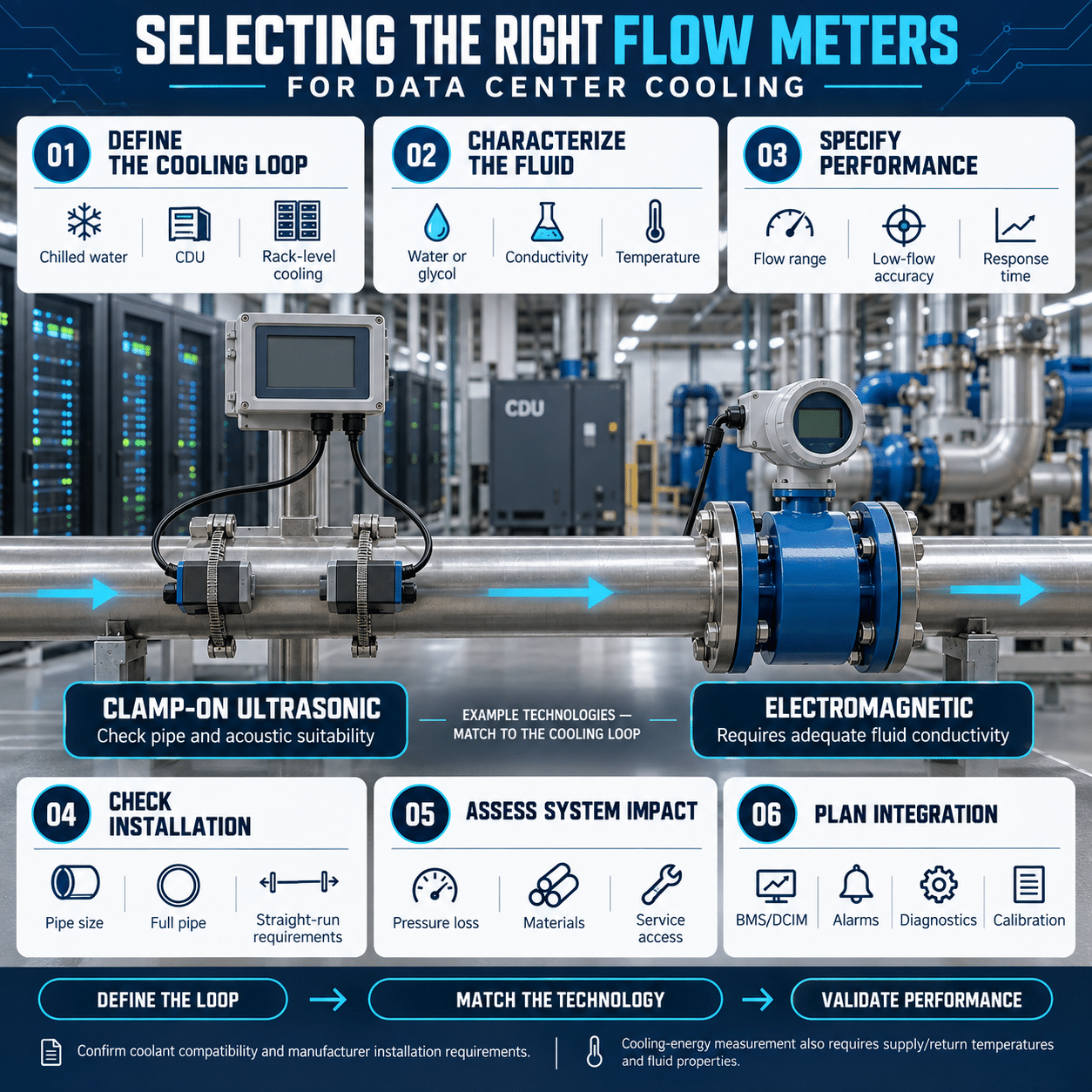
Cooling performance is critical to data center availability. As rack densities increase and liquid cooling becomes more common, operators need accurate information about how coolant moves through the facility.
Flow meters provide that visibility. They can verify cooling capacity, identify unbalanced circuits, detect changes in system performance and support energy calculations. However, a meter that performs well in a large chilled-water header may not be suitable for a coolant distribution unit or direct-to-chip loop.
Selecting the right meter requires a clear understanding of the fluid, pipe, operating range, accuracy requirement and purpose of the measurement.
Start with the measurement objective
Before choosing a technology, define what the flow measurement needs to accomplish.
Common objectives include:
- Controlling pump speed
- Balancing chilled-water branches
- Verifying flow through chillers and heat exchangers
- Monitoring coolant distribution units
- Measuring flow to data halls or individual rows
- Confirming direct-to-chip coolant delivery
- Detecting leaks or blockages
- Calculating cooling capacity
- Measuring thermal energy
- Supporting capacity planning
- Verifying commissioning results
- Comparing cooling performance over time
- Allocating energy use to tenants or departments
The measurement objective determines the required accuracy, response time, turndown and communications.
A meter used for temporary balancing does not need the same features as one used for continuous control. A meter used for billing or contractual allocation may require additional calibration, documentation and verification.
Identify the cooling loop
Data centers can contain several distinct fluid systems.
Chilled-water loop
The chilled-water loop carries cooling from the chiller plant to air handlers, computer room air handlers, rear-door heat exchangers or other cooling equipment.
Flow measurement can help verify:
- Chiller loading
- Pump performance
- Coil flow
- Branch balance
- Available cooling capacity
- Low delta-T conditions
Condenser-water loop
Condenser water transfers heat from water-cooled chillers to cooling towers or another heat-rejection system.
These loops may have:
- Larger pipe diameters
- Higher water temperature
- Open-system contamination
- Scale
- Treatment chemicals
- Entrained air
Meter selection must account for water quality and pipe condition.
Secondary liquid-cooling loop
A coolant distribution unit, or CDU, separates the facility-water system from the technology-cooling system.
The secondary loop may serve:
- Cold plates
- Direct-to-chip cooling
- In-row cooling equipment
- Rear-door heat exchangers
- High-density computing clusters
These systems can have smaller pipes, lower flow rates and tighter temperature-control requirements.
Glycol loop
Water-glycol mixtures are often used where freeze protection is required.
Glycol concentration affects:
- Density
- Specific heat
- Viscosity
- Sound velocity
- Heat-transfer performance
The meter and thermal-energy calculation must use properties appropriate for the actual concentration and temperature.
Dielectric-fluid loop
Some liquid-cooling architectures use nonconductive dielectric fluids.
Confirm that the meter’s wetted materials, measurement principle and calibration are compatible with the specific fluid. Do not assume that a meter configured for water will provide the same performance with a dielectric coolant.
Define the complete operating range
A flow meter should be selected for the complete range of expected operation, not only the design flow.
Document:
- Minimum flow
- Normal flow
- Maximum flow
- Startup flow
- Bypass flow
- Expected turndown
- Normal and maximum pressure
- Normal and maximum temperature
- Direction of flow
- Fluid density
- Fluid viscosity
- Fluid conductivity
- Glycol concentration
- Expected air or bubble content
- Water quality
- Pipe size and material
Part-load operation is especially important. A meter that performs well at design flow may provide poor resolution when pumps slow down or cooling demand falls.
Select a meter whose usable range includes the lowest flow that matters to the process.
Understand accuracy, repeatability and turndown
Several performance terms affect meter selection.
Accuracy
Accuracy describes how closely the indicated value matches the true flow.
The specification may be expressed as:
- Percentage of reading
- Percentage of full scale
- A combination of percentage and fixed error
A percentage-of-full-scale error becomes more significant at low flow. Read the complete accuracy statement rather than comparing one headline number.
Repeatability
Repeatability describes the meter’s ability to report the same value under the same conditions.
High repeatability can be especially important for control and trend monitoring, even when absolute accuracy is less critical.
Turndown
Turndown is the ratio between the maximum and minimum usable flow.
Data center systems often operate at varying loads, so adequate turndown is essential. Confirm that the meter remains accurate and stable throughout the expected range.
Response time
Fast response may be important for:
- Pump control
- Low-flow protection
- Leak detection
- CDU monitoring
- Rapid load changes
Slower response may be acceptable for energy reporting or long-term trending. Excessively fast signals can also create noisy control loops, so damping should be adjustable where practical.
Clamp-on ultrasonic flow meters
Clamp-on ultrasonic meters mount transducers on the outside of the pipe. They measure the difference in transit time between ultrasonic signals traveling with and against the flow.
Advantages include:
- No pipe penetration
- No added pressure loss
- No wetted components
- Installation without cutting the pipe
- Useful retrofit capability
- Suitability for temporary or permanent measurement
- Broad pipe-size coverage
- Bidirectional measurement in applicable models
Clamp-on meters are often well suited to:
- Existing chilled-water systems
- Large headers
- Commissioning
- Flow surveys
- Pump-performance checks
- Temporary capacity studies
- Energy audits
Performance depends on accurate information about:
- Pipe outside diameter
- Wall thickness
- Pipe material
- Liner material and thickness
- Fluid properties
- Transducer spacing
- Mounting method
Pipe condition also matters. Corrosion, scale, internal lining separation or heavy surface coating can weaken the ultrasonic signal.
The pipe must normally remain completely full. Excessive bubbles or suspended solids can interfere with signal transmission.
Fuji Electric offers clamp-on ultrasonic flow meters for permanent monitoring and portable instruments for surveys, verification and thermal-energy measurements. The Fuji Electric FSZ S-Flow is a compact, all-in-one clamp-on ultrasonic flow meter engineered specifically for small-bore piping from 3/8″ to 2″. It features an integrated transmitter and detector housing that mounts effortlessly with a four-screw clamp mechanism, completely eliminating the need for pipe cutting or process downtime. Notably, its greaseless rubber coupling pads eliminate traditional acoustic grease maintenance, ensuring highly reliable, long-term transit-time flow measurement across a variety of industrial fluids and clean liquids.
Inline ultrasonic flow meters
Inline ultrasonic meters use a spool piece installed directly in the piping. The geometry and acoustic paths are controlled by the manufacturer.
Potential advantages include:
- High accuracy
- Strong repeatability
- No moving parts
- Low pressure loss
- Bidirectional capability
- Stable factory-defined geometry
- Suitability for clean and nonconductive liquids
An inline meter may be appropriate for:
- Main cooling headers
- Critical CDU circuits
- New construction
- High-accuracy monitoring
- Permanent performance measurement
- Purified-water or nonconductive-fluid service
Installation requires cutting the pipe and may require a shutdown. The meter body, flanges and seals must meet the system’s pressure, temperature and material requirements.
Fuji Electric’s FST spool-piece ultrasonic meter uses multiple acoustic paths to improve measurement performance in supported pipe sizes and applications.
Electromagnetic flow meters
An electromagnetic flow meter uses a magnetic field and electrodes to measure the velocity of a conductive liquid.
Advantages include:
- No moving parts
- Minimal pressure loss
- Good low-flow performance
- Broad turndown
- Measurement largely independent of density and viscosity
- Suitability for treated water and water-glycol mixtures, when conductivity is sufficient
Limitations include:
- The liquid must meet minimum conductivity requirements.
- Electrodes contact the fluid.
- Liner and electrode materials must be compatible.
- Electrical grounding must be correct.
- Empty-pipe conditions can disrupt measurement.
Electromagnetic meters can be a strong choice for chilled water, condenser water and other conductive coolants.
They are generally not suitable for nonconductive dielectric fluids.
Differential pressure flow measurement
Differential pressure flow meters use a restriction, such as an orifice plate, flow nozzle or Venturi, to create a pressure difference that varies with flow.
Advantages include:
- Established technology
- Broad pressure and temperature capability
- Familiar maintenance practices
- Availability across many pipe sizes
- Compatibility with many fluids
Limitations include:
- Permanent pressure loss
- Limited low-flow sensitivity
- Impulse-line maintenance
- Greater installation complexity
- Accuracy dependence on fluid and primary-element data
A differential pressure system may be appropriate where it is already standardized or where pressure and temperature conditions favor the technology.
For energy-conscious cooling loops, permanent pressure loss should be considered carefully because it increases pump power.
Mechanical flow meters
Turbine, paddle-wheel and other mechanical meters can provide economical flow measurement in some systems.
Potential limitations include:
- Moving-part wear
- Sensitivity to debris
- Added pressure loss
- Maintenance requirements
- Changes in performance over time
- Bearing or rotor fouling
Mechanical meters may be suitable for small, clean loops, but lifecycle maintenance should be compared with nonmechanical technologies.
Coriolis flow meters
Coriolis meters measure mass flow directly and can also provide density information.
They offer high accuracy but can have:
- Higher initial cost
- Greater weight
- More pressure loss
- Limited practicality in large pipe sizes
- Installation sensitivity
They may be considered for smaller, specialized coolant loops where mass-flow accuracy or fluid-property measurement justifies the cost.
Match the meter to the fluid
The fluid affects every measurement technology.
For each loop, define:
- Chemical composition
- Glycol type and concentration
- Corrosion inhibitors
- Water-treatment chemicals
- Conductivity
- Viscosity
- Density
- Specific heat
- Sound velocity
- Bubble content
- Suspended solids
- Material compatibility
For ultrasonic meters, the liquid must transmit acoustic energy effectively. Fluid sound velocity, pipe material and pipe dimensions must be entered correctly.
For electromagnetic meters, conductivity must exceed the meter’s minimum requirement.
For meters with wetted components, verify compatibility with seals, liners, electrodes and meter bodies.
Account for pipe material and condition
Flow measurement is influenced by the pipe.
Relevant factors include:
- Nominal size
- Actual outside diameter
- Wall thickness
- Schedule
- Material
- Lining
- Insulation
- Internal scale
- Corrosion
- Surface condition
- Weld seams
Clamp-on ultrasonic meters require especially accurate pipe data. Nominal dimensions may not match the installed pipe, particularly in older systems.
Remove external paint, rust or loose scale from the transducer mounting location as required. Use the specified acoustic coupling material and mounting hardware.
If the pipe has a liner, both liner thickness and acoustic properties may affect signal quality.
Select the correct meter size
Selecting a meter solely by pipe diameter can reduce measurement quality.
The meter should operate within its recommended velocity range at minimum, normal and maximum flow.
An oversized meter can produce low velocity and poor low-flow resolution. An undersized meter can create excessive pressure loss and may exceed the meter’s velocity limit.
For inline meters, consider reducing the meter size only when:
- Pressure loss is acceptable
- Reducers are installed correctly
- Cavitation is not a concern
- Straight-run requirements are met
- Maximum velocity remains within limits
The piping and meter should be designed as one hydraulic system.
Provide adequate straight pipe
Elbows, valves, pumps, tees and reducers can distort the velocity profile.
Distortion can include:
- Swirl
- Asymmetric flow
- Turbulence
- Pulsation
- Separation
Follow the manufacturer’s upstream and downstream straight-run requirements.
Avoid installing a meter immediately downstream of:
- A pump discharge
- A control valve
- Multiple out-of-plane elbows
- A partially open isolation valve
- A tee
- A sudden expansion
If space is limited, consider:
- A flow conditioner
- A multipath meter
- A different measurement location
- A technology less sensitive to profile distortion
A control valve is generally better placed downstream of the meter when the application allows it.
Keep the pipe full
Many liquid flow meters assume a completely full pipe.
Avoid locations where air can collect, such as the highest point of a horizontal system. A vertical pipe with upward flow can help keep the line full.
For horizontal piping, transducers or electrodes are often positioned to avoid sediment at the bottom and air at the top. The exact orientation depends on the meter.
Potential sources of bubbles include:
- Low system pressure
- Pump suction problems
- Poor air separation
- Leaks
- Maintenance activity
- Rapid pressure reduction
- Improper expansion-tank operation
Bubble-related measurement errors may reveal a hydraulic problem that also affects cooling performance.
Measure thermal energy correctly
Cooling capacity can be estimated from flow and temperature difference:
[
\dot{Q} = \rho \times c_p \times \dot{V} \times \Delta T
]
where:
- (\dot{Q}) is thermal power
- (\rho) is fluid density
- (c_p) is specific heat
- (\dot{V}) is volumetric flow
- (\Delta T) is the supply-to-return temperature difference
Accurate thermal-energy measurement requires more than an accurate flow meter.
The complete system should include:
- Correct fluid properties
- Matched temperature sensors
- Proper sensor placement
- Sufficient immersion
- Consistent sensor mounting
- Accurate time synchronization
- Correct supply and return assignment
- Suitable calculation and totalization
Temperature uncertainty becomes especially important when delta T is small. An error of a fraction of a degree can produce a significant energy error in a low-delta-T system.
For glycol mixtures, density and specific heat should reflect actual concentration and temperature.
Fuji Electric ultrasonic flow instruments can support cooling and thermal-energy measurement in applicable configurations using flow and supply and return temperature inputs.
Consider direct-to-chip cooling
Direct-to-chip cooling presents different measurement challenges from conventional chilled water.
These systems may have:
- Smaller pipe diameters
- Lower individual circuit flows
- Higher coolant temperatures
- Narrow flow tolerances
- Water-glycol mixtures
- Deionized water
- Rapid load changes
- Parallel branches
- High sensitivity to blockage
Meter selection should consider:
- Low-flow accuracy
- Fast response
- Minimal pressure loss
- Compact size
- Fluid cleanliness
- Material compatibility
- Leak risk
- Communication with the CDU controller
A meter suitable for the facility-water side may not provide enough resolution on the technology-cooling side.
Measurement locations may include:
- CDU primary inlet
- CDU primary outlet
- CDU secondary supply
- CDU secondary return
- Rack branch
- Individual coolant loop
Measuring every branch provides detailed visibility but increases cost and system complexity. Select measurement points based on control, protection and diagnostic value.
Monitor condenser-water systems carefully
Condenser-water systems may contain scale, corrosion products, treatment chemicals and biological growth.
These conditions can affect:
- Electrode surfaces
- Ultrasonic signal quality
- Mechanical components
- Pipe roughness
- Meter calibration
- Straight-run assumptions
A clamp-on meter avoids wetted components, but heavy scale or pipe-wall deterioration can weaken its signal.
An electromagnetic meter can tolerate many dirty-water conditions, but its liner and electrodes must be compatible with the treatment chemistry.
Provide access for inspection and verification.
Plan for redundancy and failure behavior
Flow data may be used for monitoring, control or protection. The required failure strategy depends on its role.
If a flow signal controls pump speed, define what happens when the signal is lost.
Possible responses include:
- Hold the last valid command
- Move to a fixed fallback speed
- Switch to differential-pressure control
- Start a standby pump
- Generate an alarm
- Stop equipment safely
- Use a redundant sensor
For critical cooling paths, consider whether one failed meter could interrupt cooling unnecessarily.
The control system should distinguish among:
- Zero flow
- Low flow
- Sensor fault
- Communications failure
- Empty pipe
- Invalid signal
A failed sensor should not appear as a believable zero-flow value without an accompanying diagnostic.
Select the required outputs and communications
Common meter outputs include:
- 4 to 20 mA
- Pulse
- Frequency
- Relay alarm
- HART
- RS-485
- Modbus
- Ethernet-based protocols
Choose the interface that fits the BMS, PLC, CDU controller or energy-management platform.
Define the required data points, such as:
- Instantaneous flow
- Totalized flow
- Flow direction
- Thermal power
- Total energy
- Signal quality
- Meter status
- Alarm state
- Empty-pipe indication
- Sensor fault
Analog output provides a straightforward control signal. Digital communications can provide additional diagnostics and totalized values.
For critical control, some designs use a hardwired analog signal while collecting diagnostics through a digital network.
Consider power and network resilience
A meter cannot support cooling control if it loses power during an electrical disturbance.
Review:
- AC or DC power
- Available UPS-backed supply
- Voltage tolerance
- Surge protection
- Power consumption
- Network redundancy
- Controller behavior after restart
- Data retention
- Time synchronization
Meters supporting critical cooling functions may need power from a backed-up control circuit.
After a power interruption, verify that the meter restarts automatically, restores its configuration and produces a valid signal within the required time.
Use portable meters during commissioning
A portable clamp-on ultrasonic meter is useful for:
- Verifying design flow
- Checking pump curves
- Balancing branches
- Testing control-valve performance
- Investigating low delta T
- Comparing installed meters
- Identifying unexpected bypass flow
- Performing temporary energy studies
Portable measurements depend on correct setup and installation. Record:
- Pipe dimensions
- Pipe material
- Fluid
- Transducer spacing
- Mounting method
- Signal quality
- Flow direction
- Test location
- Operating conditions
A portable meter is a valuable diagnostic tool, but it should not automatically be treated as a calibration standard unless its uncertainty and setup support that use.
Commission every permanent meter
Commissioning should verify the complete measurement chain.
Check:
- Model and range
- Pipe data
- Fluid configuration
- Installation orientation
- Transducer spacing
- Straight-run compliance
- Full-pipe condition
- Flow direction
- Zero-flow behavior
- Analog scaling
- Pulse value
- Communications mapping
- Alarm settings
- Totalizer operation
- Temperature inputs
- Thermal-energy calculation
- BMS display
- Trend recording
Compare the reading with another credible reference where practical.
Record the baseline signal quality for ultrasonic meters. A future decline can indicate coupling deterioration, pipe changes or fluid problems.
Maintain measurement accuracy
Flow meters with no moving parts still require periodic attention.
A maintenance program may include:
- Inspecting transducer mounts
- Renewing acoustic coupling material where required
- Checking cable condition
- Inspecting grounding
- Reviewing signal strength
- Verifying zero and span
- Comparing redundant or portable readings
- Checking temperature sensors
- Inspecting for condensation
- Confirming pipe remains full
- Reviewing diagnostic alarms
Trend the relationship among flow, pump speed, differential pressure and power. A change can reveal fouling, valve problems, air in the system or sensor drift.
Avoid common selection mistakes
Selecting by pipe size alone
The meter must also fit the flow range, fluid and measurement objective.
Ignoring minimum flow
A meter that performs well at design flow may be ineffective during normal part-load operation.
Using clean-water assumptions for glycol
Glycol changes density, viscosity, sound velocity and heat capacity.
Overlooking pipe condition
Scale, corrosion and liners can affect ultrasonic measurement.
Treating catalog accuracy as installed accuracy
Installation, pipe data, flow profile and temperature measurement all contribute to uncertainty.
Ignoring pressure loss
An intrusive meter can increase pump energy throughout its service life.
Installing too close to a disturbance
Valves, elbows and pumps can distort the velocity profile.
Measuring flow without temperature quality
Poorly matched temperature sensors can dominate thermal-energy error.
Assuming zero flow means sensor failure
The system may have a closed valve, stopped pump, blocked line or air-bound condition.
Assuming a sensor fault means zero flow
Control logic must distinguish an invalid signal from a valid no-flow condition.
Flow-meter selection checklist
Before selecting a flow meter for data center cooling, confirm:
- What decision or control action will the measurement support?
- Which cooling loop will be measured?
- What is the fluid composition?
- What are the minimum, normal and maximum flows?
- What accuracy and repeatability are required?
- What response time is required?
- Is bidirectional measurement needed?
- What are the pipe material, size and wall thickness?
- Is the pipe lined, scaled or corroded?
- Will the pipe remain full?
- Are bubbles or suspended solids expected?
- Is sufficient straight pipe available?
- How much pressure loss is acceptable?
- Is a clamp-on or inline installation preferred?
- Is thermal-energy measurement required?
- Are the temperature sensors matched and correctly located?
- What outputs and protocols are required?
- Will the meter receive backed-up power?
- What should happen if the signal is lost?
- How will the meter be commissioned and verified?
Select the meter as part of the cooling system
The right flow meter provides more than a number on a screen. It helps operators understand whether cooling capacity is reaching the correct equipment at the correct time.
Clamp-on ultrasonic meters can simplify retrofits and temporary studies. Inline ultrasonic meters can provide high accuracy with low pressure loss. Electromagnetic meters can deliver strong performance for conductive cooling fluids, while other technologies can address specialized requirements.
Fuji Electric offers portable, clamp-on, integral and spool-piece ultrasonic flow-meter solutions for cooling water, purified water, glycol mixtures and other compatible fluids. By matching the measurement technology to the fluid, pipe, operating range and purpose, data center operators can improve cooling visibility, energy management and system reliability.