
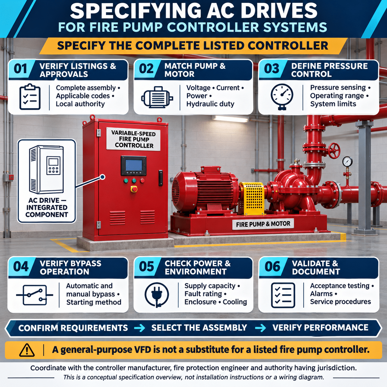
Fire pumps serve a life-safety function. When a sprinkler, standpipe, or other fire-protection system demands water, the pump must start and continue operating under conditions that would shut down many conventional motor-driven systems.
Variable-speed fire pump controllers use an AC drive, also known as an adjustable speed drive or variable frequency drive, to regulate motor speed and maintain a controlled discharge pressure. This can be valuable in high-rise buildings, warehouses, hospitals, campuses, and other facilities where a constant-speed pump would create excessive pressure at lower flow rates.
However, specifying an AC drive for a fire pump controller is fundamentally different from selecting a drive for an ordinary HVAC or process-water pump. The drive is only one component of a complete fire pump controller, and the assembled controller must satisfy the applicable fire-protection codes, product standards, listing requirements, and requirements of the authority having jurisdiction.
Why Use Variable-Speed Control on a Fire Pump?
A centrifugal fire pump operating at constant speed follows a characteristic pump curve. Discharge pressure is generally highest at low flow and decreases as flow increases.
In systems with large elevation changes or widely varying demand, this characteristic can create excessive pressure under lower-flow conditions. Designers may otherwise need pressure-reducing valves, multiple pressure zones, or other hydraulic measures to keep system pressure within acceptable limits.
A variable-speed controller can reduce pump speed when full pressure is not required. Using feedback from the fire-protection system, the controller adjusts motor frequency to maintain the required pressure over a defined operating range.
The relationship between pump speed and hydraulic performance can be approximated by the pump affinity laws:
Q2 = Q1 * N2/N1
H2 = H1 * (N2/N1)^2
P2 = P1 * (N2/N1)^3
Where:
- (Q) is flow
- (H) is pump head
- (P) is hydraulic power
- (N) is pump speed
A relatively small reduction in speed can therefore produce a meaningful reduction in discharge pressure. This allows the controller to regulate system pressure without continuously dissipating excess pressure across a valve.
Variable-speed control may also provide a smoother acceleration profile during normal drive operation, reducing mechanical shock and limiting motor-starting current. These benefits are useful, but they are secondary to the fire pump’s primary responsibility, delivering the required water supply during an emergency.
Begin With the Listed Fire Pump Controller
An individual AC drive should not be treated as a stand-alone fire pump controller. A general-purpose drive installed in a conventional control panel does not automatically create a compliant fire pump controller.
The complete assembly must be designed, evaluated, labeled, and installed for fire pump service. Depending on the jurisdiction and project, requirements may include:
- NFPA 20, Standard for the Installation of Stationary Pumps for Fire Protection
- NFPA 70, National Electrical Code
- UL 218, Standard for Fire Pump Controllers
- Applicable building and fire codes
- Requirements established by the authority having jurisdiction
- Insurer or owner specifications
The adopted editions can differ among jurisdictions. The engineer should identify the applicable requirements early and coordinate with the controller manufacturer, fire-protection designer, electrical engineer, and authority having jurisdiction.
The AC drive must be selected as part of the listed controller design. Substituting a different drive model after the controller has been evaluated may affect the controller’s listing, short-circuit rating, thermal performance, control logic, or emergency operating sequence.
Understand the Required Operating Sequence
The controller must recognize a demand for fire protection and start the pump automatically when required. In a variable-speed system, the drive then adjusts motor speed to maintain the specified pressure.
The intended sequence should define:
- How a pressure drop initiates pump operation
- How the controller establishes the pressure setpoint
- How quickly the drive accelerates the motor
- How minimum and maximum speed are limited
- How the system responds to loss of the pressure signal
- What conditions initiate bypass operation
- How manual emergency operation is performed
- Whether stopping is manual or automatic under the applicable design
- How alarms and status signals are communicated
Fire pump logic must prioritize water delivery. Control features that are appropriate for normal process pumps, such as aggressive energy optimization, sleep modes, dry-pump shutdown, or automatic shutdown on ordinary motor faults, may be inappropriate or prohibited in fire pump service.
The complete controller manufacturer must determine which protective functions are permitted, how they operate, and whether they alarm, transfer to bypass, or allow continued operation.
Specify the Drive by Motor Current
Drive selection should start with the fire pump motor nameplate and controller requirements.
Collect the following information:
- Motor horsepower or kilowatt rating
- Rated voltage
- Full-load current
- Rated frequency
- Number of phases
- Motor speed and pole count
- Service factor
- Locked-rotor code or starting-current data
- Motor insulation system
- Ambient temperature rating
- Expected maximum operating load
The drive should be selected by output-current capability, not horsepower alone. Two motors with the same horsepower may have different full-load currents, efficiencies, service factors, or operating characteristics.
The selected drive must support the motor current required throughout the approved pump operating range. It must also satisfy the overload, thermal, and test requirements applied to the complete listed fire pump controller.
A larger drive may be necessary when:
- The motor full-load current exceeds the nominal drive rating
- The enclosure temperature requires derating
- The installation is at high altitude
- The carrier-frequency setting reduces available output current
- The drive must support specified overload conditions
- The controller design limits airflow or heat dissipation
- The motor operates near its service-factor load
- Harmonic mitigation equipment changes thermal conditions
Oversizing should still be coordinated with the controller manufacturer. A larger drive can affect enclosure dimensions, branch-circuit components, bypass equipment, cooling requirements, short-circuit coordination, and listing documentation.
Confirm Voltage and Power-System Compatibility
The drive and controller must match the available electrical service.
Evaluate:
- Nominal system voltage
- Permitted voltage variation
- Available fault current
- Source transformer capacity
- Generator characteristics
- Phase imbalance
- Voltage drop during motor starting
- Automatic transfer equipment
- Grounding method
- Frequency
- Emergency-power arrangement
Fire pump power supplies are subject to specific reliability and routing requirements. The controller must function with the actual source characteristics, including conditions that may occur during a fire.
When an emergency generator supplies the fire pump, the generator must support both the variable-speed operating mode and the bypass starting method. A drive may reduce current during controlled acceleration, but the generator cannot be sized solely around that reduced starting current if the system can transfer to across-the-line bypass operation.
The generator, conductors, transfer equipment, and upstream distribution system should be evaluated for the most demanding approved operating condition.
Provide a Suitable Bypass
A variable-speed fire pump controller commonly includes a bypass that can connect the motor directly to the power source if the drive becomes unavailable. This bypass is a critical reliability feature, not merely a maintenance convenience.
The controller design should clearly establish:
- Automatic bypass conditions
- Manual bypass operation
- Mechanical emergency operation
- Interlocking between drive and bypass paths
- Across-the-line starting capability
- Status indication
- Alarm behavior
- Operation following pressure-feedback failure
- Procedure for returning from bypass to drive control
When the controller transfers to bypass, the pump normally operates at full line frequency and approximately full rated speed. The hydraulic system must therefore be capable of handling the resulting pressure.
Variable-speed regulation should not be used to conceal an unsafe constant-speed system condition. The pump, piping, fittings, valves, sprinkler components, and other equipment must be evaluated for the pressure that can occur during bypass operation, including churn conditions and elevation effects.
Coordinate the Drive With the Pump Curve
The AC drive cannot be specified independently of the fire pump and water supply.
Review:
- Rated pump flow
- Rated pressure
- Churn pressure
- Pump power demand across the curve
- Maximum permitted pump load
- Available suction pressure
- Minimum suction pressure
- Required system pressure
- Elevation changes
- Flow demands for sprinklers, standpipes, and hose streams
- Pressure limits of downstream equipment
The drive must allow the pump to reach full rated speed and deliver the required rated and overload flow conditions. The controller’s pressure-regulating function must not prevent the pump from satisfying system demand.
Particular attention should be given to suction pressure. If suction pressure changes significantly, a control strategy based only on discharge pressure may not adequately represent net pump pressure. The complete system design should account for the permitted control method and the hydraulic conditions at both pump connections.
Design the Pressure-Control Loop Carefully
Stable pressure regulation depends on more than the drive’s internal PID function. The pressure sensor, sensing-line location, controller logic, pump dynamics, and piping system all affect performance.
The pressure measurement should:
- Cover the expected operating range
- Withstand maximum system and surge pressure
- Provide suitable accuracy and response
- Use compatible wetted materials
- Be installed at the approved sensing location
- Be protected against blockage, freezing, leakage, and mechanical damage
- Produce a signal compatible with the controller
The PID loop should be tuned to avoid hunting, overshoot, and repeated speed changes. An overly aggressive response can create pressure oscillation or water hammer. A response that is too slow may allow pressure to fall below the required level when demand increases rapidly.
Important drive parameters may include:
- Minimum frequency
- Maximum frequency
- Acceleration rate
- Deceleration behavior
- Proportional gain
- Integral time
- Feedback scaling
- Feedback-loss response
- Pressure setpoint
- Motor data
- Current limits approved for the application
These values should be established and protected as part of the controller design. Unauthorized changes to drive parameters could alter the fire pump’s performance.
Evaluate Motor and Cable Compatibility
Pulse-width-modulated drive output places different electrical stresses on a motor than sinusoidal utility power. Fast voltage transitions can produce reflected-wave effects, particularly when the motor cable is long.
Confirm:
- Motor suitability for inverter operation
- Motor insulation rating
- Cable type and length
- Drive-to-motor distance
- Grounding and bonding
- Need for a load reactor
- Need for a dV/dt or sine-wave filter
- Motor bearing-current risk
- Compatibility of output filters with bypass operation
Any output reactor or filter must be included in the controller’s evaluated design. Its voltage drop, heat generation, fault behavior, and effect on both drive and bypass operation must be considered.
The motor circuit should follow the controller manufacturer’s approved wiring arrangement. Contactors should not be added between the drive and motor unless they are part of the tested controller design and operate in the intended sequence.
Address Harmonics and Power Quality
The input rectifier of a conventional AC drive draws nonsinusoidal current. The resulting harmonic currents can contribute to voltage distortion in the electrical system.
A power-quality study may be appropriate when:
- The fire pump motor is large relative to the service transformer
- Several drives share the same electrical system
- The pump is supplied by a generator
- Sensitive equipment is connected nearby
- The facility imposes harmonic limits
- The source has relatively high impedance
Possible mitigation measures include:
- AC line reactors
- DC-link reactors
- Passive harmonic filters
- Multipulse arrangements
- Active harmonic filters
- Alternative low-harmonic drive topologies
Harmonic mitigation should be evaluated at the point of common coupling and under realistic loading conditions. Because fire pumps operate infrequently, the project should distinguish between normal standby conditions, test operation, and emergency operation.
All mitigation equipment in the fire pump power path must be compatible with the controller listing and the reliability requirements of the installation.
Select the Correct Enclosure and Cooling Arrangement
Fire pump controllers are commonly installed in dedicated pump rooms, but these spaces can still be hot, humid, dusty, or exposed to water.
Define:
- Minimum and maximum ambient temperature
- Humidity and condensation
- Elevation
- Water exposure
- Corrosive substances
- Dust and airborne contaminants
- Ventilation
- Required enclosure type
- Seismic requirements
- Available service clearances
The drive produces heat even when operating efficiently. The controller manufacturer should calculate enclosure losses and verify that internal temperatures remain within the ratings of the drive, contactors, control transformer, sensing equipment, and other components.
Cooling fans, filters, heat exchangers, or air-conditioning equipment can introduce maintenance requirements. The design should consider what happens if the normal enclosure-cooling system is impaired during an emergency.
Consider Electromagnetic Compatibility
Drive switching can create conducted and radiated electrical noise. Poor installation practices may interfere with pressure feedback, alarms, communication networks, or other building systems.
Good design practices include:
- Separating power and signal wiring
- Using appropriate shielded cable
- Terminating shields according to the approved design
- Providing low-impedance grounding and bonding
- Keeping pressure-sensor wiring away from motor leads
- Minimizing motor-cable length
- Using approved filters or reactors where needed
- Protecting control circuits from electrical surges
- Verifying signal behavior during drive operation
The pressure-feedback signal is particularly important because electrical noise can appear as a false pressure fluctuation and cause unstable speed commands.
Define Communications Without Compromising Local Control
A fire pump controller may provide information to a building management system, fire alarm system, or supervisory platform. Useful signals can include:
- Pump running
- Controller in automatic mode
- Drive operating
- Bypass operating
- Phase failure
- Phase reversal
- Power available
- Drive fault
- Pressure
- Motor current
- Controller trouble
Remote monitoring can improve visibility, but it should not become a dependency for essential fire pump operation. Loss of a network, building automation controller, or supervisory computer must not prevent the local controller from starting and operating the pump as required.
Remote commands should be limited to functions permitted by the applicable codes and approved controller design.
Specify Appropriate Drive Reliability Features
Fire pump applications place a premium on predictable operation and long service life. Useful drive characteristics include:
- Adequate current and overload capacity
- Stable PID control
- Reliable operation across the specified voltage range
- Clear diagnostic information
- Replaceable cooling fans
- Long-life DC-bus components
- Parameter backup and restoration
- Event and fault records
- Local status display
- Supported spare parts
- Long-term product availability
- Qualified technical support
Drive diagnostics can simplify maintenance, but fault handling must follow the controller’s approved fire pump logic. A drive fault that would shut down an ordinary process pump may instead require an alarm and transfer to bypass.
Fuji Electric’s FRENIC-MEGA platform is used by fire pump controller manufacturers for variable-speed control. Its motor-control performance, PID capability, broad horsepower range, and diagnostic functions can support fire pump applications when incorporated into an appropriately engineered and listed controller.
The final drive model, rating, firmware, parameter set, cooling method, and accessories should be selected by the controller manufacturer as part of the complete certified assembly.
Require Complete Submittal Information
A fire pump controller submittal should include enough information for the engineer and authority having jurisdiction to verify the design.
Typical documentation includes:
- Controller listing and certification information
- Applicable standards
- Controller model and rating
- AC drive manufacturer and model
- Motor horsepower, voltage, and current
- Pump data and certified curve
- Power and control wiring diagrams
- Drive and bypass sequence of operation
- Pressure-control description
- Enclosure type
- Short-circuit current rating
- Heat-loss information
- Required clearances
- Input and output reactor or filter details
- Alarm and communication points
- Generator compatibility information
- Field testing procedure
- Maintenance instructions
- Recommended spare parts
Any deviation from the submitted drive or controller configuration should be reviewed before installation.
Commission the Complete System
Commissioning should evaluate the fire pump, motor, drive, controller, bypass, pressure sensing, water supply, and electrical source as one system.
Testing should verify:
- Automatic pump starting
- Manual operation
- Pressure regulation at multiple flow rates
- Full-speed operation
- Bypass operation
- Transition to bypass under the intended conditions
- Pressure-sensor failure response
- Operation at rated pump flow
- Operation at required overload flow
- Churn pressure
- Motor voltage and current
- Phase conditions
- Generator operation, where applicable
- Alarm and supervisory signals
- Parameter security
- Emergency manual controls
Pressure should be measured at the required points, and actual performance should be compared with the approved pump curve and system design.
The test should also confirm that operation at full speed or in bypass does not create unacceptable system pressure.
Plan for Inspection and Maintenance
An AC drive adds electronic components, cooling devices, control parameters, and diagnostic functions to the fire pump controller. These elements should be included in the inspection, testing, and maintenance program.
Maintenance activities may include:
- Inspecting and cleaning ventilation paths
- Checking cooling-fan condition
- Examining power connections for overheating
- Inspecting capacitors for signs of deterioration
- Verifying pressure-transducer performance
- Testing drive and bypass modes
- Reviewing alarm and fault history
- Confirming parameter settings
- Checking surge-protection devices
- Exercising mechanical emergency controls
- Maintaining environmental conditions in the pump room
Only qualified personnel should alter drive settings or replace controller components. Replacement parts and firmware should remain consistent with the controller manufacturer’s approved configuration.
Fire Pump AC Drive Specification Checklist
Before approving an AC drive fire pump controller, confirm:
- The complete controller is listed for the intended fire pump application.
- The applicable code editions and local amendments have been identified.
- The authority having jurisdiction has reviewed the proposed arrangement.
- The drive is sized by motor current and actual operating requirements.
- Voltage, frequency, phase, and power-source characteristics are compatible.
- The available fault current does not exceed the controller rating.
- The generator can support the required drive and bypass conditions.
- The bypass provides the required automatic and manual operating functions.
- The hydraulic system can withstand full-speed and churn pressure.
- The drive can operate the pump across the required flow range.
- The pressure sensor and control loop are suitable for the application.
- Motor insulation and cable length are compatible with drive output.
- Harmonics and electromagnetic interference have been evaluated.
- Environmental conditions and enclosure cooling are addressed.
- Required alarms and supervisory signals are provided.
- Commissioning includes both variable-speed and bypass operation.
- Inspection and maintenance responsibilities are documented.
Reliability Must Guide the Specification
Variable-speed control can help maintain a more consistent fire-protection-system pressure, reduce mechanical stress during controlled starts, and provide useful operating diagnostics. Those advantages are meaningful only when the drive is integrated without weakening the fire pump system’s essential reliability.
The correct specification begins with the complete listed fire pump controller, not with a stand-alone drive. Motor current, hydraulic performance, power-source capacity, bypass operation, pressure regulation, environmental conditions, and code compliance must be evaluated together.
When these requirements are coordinated from the beginning, a Fuji Electric AC drive can provide precise motor control within a fire pump controller engineered to deliver dependable water pressure when the building’s fire-protection system needs it most.