
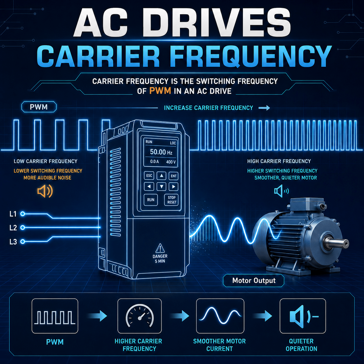
Carrier frequency is one of the most misunderstood settings on a variable frequency drive (VFD). Increase it, and the motor often becomes quieter. Decrease it, and the drive may run cooler and more efficiently. That makes the setting look like a simple choice between noise and heat, but the real tradeoff also involves cable length, motor insulation, bearing currents, electromagnetic interference, and the VFD’s current capacity.
Understanding those relationships is essential when commissioning a drive or troubleshooting a motor system.
What Is Carrier Frequency?
A VFD controls an AC motor by rapidly switching its output transistors on and off. This technique, known as pulse-width modulation (PWM), creates an effective waveform with the voltage and frequency needed to regulate motor speed and torque.
The carrier frequency, also called switching frequency, is the rate at which those transistors switch. Depending on the drive, motor, and application, it commonly falls within a range of a few kilohertz to the low tens of kilohertz.
Carrier frequency is not the same as the motor’s electrical output frequency. A motor might operate at 60 Hz while the VFD switches thousands of times per second to synthesize that output.
Why Higher Carrier Frequencies Sound Quieter
The familiar whine produced by a VFD-driven motor is largely associated with electromagnetic forces generated by the PWM waveform. These forces can excite the motor’s laminations, windings, and mechanical structure.
At lower carrier frequencies, the switching-related sound may fall within the most sensitive part of human hearing. Raising the carrier frequency shifts much of that tonal noise upward, making the motor sound quieter or changing the noise into a less noticeable pitch.
This can be valuable in applications such as:
- Office and residential HVAC systems
- Elevators
- Theaters and studios
- Laboratories
- Occupied manufacturing areas
- Equipment located near customers or operators
A quieter motor, however, is not necessarily a healthier or more efficient motor. The acoustic improvement comes with electrical and thermal consequences elsewhere in the system.
The Heating Tradeoff
Every transistor switching event produces some energy loss inside the VFD. Raising the carrier frequency increases the number of switching events per second, so drive losses generally rise.
That additional loss becomes heat.
At higher carrier frequencies, a drive may require:
- Output-current derating
- Lower ambient temperatures
- Improved enclosure ventilation
- Larger cooling fans or heat sinks
- Selection of a higher-capacity drive
The exact derating requirements depend on the VFD model. Two drives with the same horsepower rating may have very different carrier-frequency limits and thermal characteristics, so the manufacturer’s current-versus-carrier-frequency data should always take priority over a generic rule.
Higher carrier frequency can sometimes reduce certain low-frequency harmonic effects and associated motor losses. Even so, it does not guarantee a cooler motor. Motor temperature is also affected by load, speed, cooling method, cable characteristics, PWM waveform quality, and the motor’s design.
At low operating speeds, a standard self-cooled motor is especially vulnerable because its shaft-mounted fan is turning slowly. Carrier-frequency adjustments cannot compensate for inadequate motor cooling under sustained high-torque, low-speed operation.
Motor Stress Is About More Than Temperature
A VFD’s output is not a smooth sine wave. Its voltage changes in fast pulses with steep rise times. At the motor terminals, those pulses can create voltage stress that exceeds what might be expected from the DC bus voltage alone.
Cable impedance and pulse reflections can amplify the terminal voltage, particularly when the cable between the VFD and motor is long. The resulting repetitive voltage peaks place stress on winding insulation.
Carrier frequency influences how often the motor experiences these pulses. Increasing the setting means more voltage transitions per second. Although carrier frequency is not the only factor governing peak voltage, a higher switching rate can increase the cumulative electrical stress and common-mode activity imposed on the motor system.
Important variables include:
- Cable length
- Cable construction and shielding
- Motor insulation rating
- Pulse rise time
- DC bus voltage
- Grounding and bonding
- Output reactor or filter selection
- Motor lead routing
- Carrier frequency
This is why a high carrier frequency that works well with a short motor cable may be inappropriate for the same motor installed hundreds of feet from the drive.
Bearing Currents and Common-Mode Voltage
PWM drives generate common-mode voltage, which can create unwanted current paths through motor bearings. If shaft voltage becomes high enough to discharge through the bearing lubricant, microscopic electrical damage can occur.
Over time, repeated discharges may contribute to:
- Bearing pitting
- Frosting
- Fluting
- Increased vibration
- Audible bearing noise
- Premature bearing failure
Higher carrier frequencies can increase the frequency of common-mode voltage transitions and bearing-current events. Whether damage occurs depends on the complete installation, not merely the number entered in the carrier-frequency parameter.
Mitigation may include insulated bearings, shaft-grounding devices, properly terminated shielded cable, common-mode chokes, output filters, and sound grounding and bonding practices. These measures should be selected as part of a coordinated system design.
Electromagnetic Interference
Faster and more frequent switching also increases the system’s high-frequency electrical activity. That energy can couple into nearby control wiring, communications networks, sensors, encoders, and building systems.
Symptoms may include:
- Unstable analog signals
- Encoder count errors
- Intermittent communication faults
- Nuisance trips
- Erratic sensor readings
- Radio-frequency interference
Raising carrier frequency may make a motor more pleasant to hear while making the installation electrically noisier. Cable separation, shielding, grounding, enclosure design, and filter selection therefore become more important as switching frequency increases.
Is a Lower Carrier Frequency Always Better?
No. Lower settings reduce VFD switching losses and often allow the drive to deliver more current without derating. They may also reduce some high-frequency system stresses.
But an excessively low carrier frequency can introduce its own problems:
- More audible motor noise
- Greater torque ripple in some operating conditions
- Rougher low-speed performance
- Increased motor vibration
- Less acceptable performance in noise-sensitive environments
The correct objective is not to minimize or maximize carrier frequency. It is to use the lowest setting that still provides acceptable acoustic and control performance for the application.
Common Carrier-Frequency Myths
“Set it as high as possible for smoother power.”
A higher setting may improve audible noise and sometimes perceived smoothness, but the VFD output remains PWM. Increasing carrier frequency also increases switching losses and can require current derating.
“If the motor is quiet, the setting must be safe.”
Acoustic noise reveals very little about winding insulation stress, bearing currents, common-mode voltage, or drive temperature. A quiet installation can still experience significant electrical stress.
“Carrier frequency only affects the motor.”
It affects the entire system: VFD losses, enclosure temperature, cable behavior, electromagnetic compatibility, filters, bearings, and sometimes the available output current.
“One setting works for every motor on the drive.”
Motor design, cable length, load profile, ambient conditions, and required speed range can all change the appropriate setting.
“The factory default is always optimal.”
The default is normally a broadly usable compromise, not a guarantee of optimal performance for a particular installation.
A Practical Selection Process
A disciplined approach is more reliable than choosing a value based solely on sound.
1. Start with the manufacturer’s guidance
Review the VFD manual for:
- Permitted carrier-frequency range
- Current derating curves
- Ambient-temperature restrictions
- Maximum recommended motor-cable length
- Restrictions for multiple-motor applications
- Required reactors or filters
Also confirm that the motor is suitable for inverter duty and for the system voltage.
2. Begin near the recommended default
The default usually balances noise, thermal performance, and current capacity. It is a sensible commissioning baseline unless the application documentation specifies otherwise.
3. Confirm the real operating conditions
Evaluate the system at its highest continuous load, lowest sustained speed, highest expected ambient temperature, and other demanding operating points. A setting that works during a brief unloaded test may fail in normal production.
4. Increase only when there is a clear benefit
If audible noise is unacceptable, raise the carrier frequency gradually and remain within the manufacturer’s limits. After each change, check drive temperature, motor current, motor temperature, and fault history.
5. Evaluate the installation as a system
Long motor cables, older motors, high system voltages, parallel motors, and sensitive nearby electronics deserve additional attention. Output reactors, dV/dt filters, or sine-wave filters may be more appropriate than relying on parameter changes alone.
6. Document the final setting
Record the selected value, reason for the change, load conditions, temperatures, cable length, and any derating applied. This gives future technicians a technical basis for the setting instead of leaving behind an unexplained parameter change.
When Filters Become Necessary
Carrier-frequency adjustment has limits. When motor leads are long or the motor insulation is vulnerable, an output device may be required.
Common options include:
- Output reactors: Add impedance and can reduce current ripple and the severity of some voltage effects.
- dV/dt filters: Reduce the rate of voltage change and help protect motor insulation.
- Sine-wave filters: Produce an output closer to a sinusoidal waveform and can substantially reduce motor noise and electrical stress.
- Common-mode filtering: Helps control common-mode currents and related interference.
Filter selection must account for voltage, current, output frequency, cable length, and the VFD manufacturer’s requirements.
The Bottom Line
Carrier frequency is a system-level engineering compromise.
Raising it can make the motor quieter, but it generally increases VFD switching losses and may require derating. It can also increase the number of high-frequency voltage transitions affecting motor insulation, bearings, cables, and nearby electronics.
Lowering it can improve drive thermal margin and reduce certain high-frequency effects, but it may increase audible noise, vibration, or torque ripple.
The best setting is therefore not the highest available value or the quietest one. It is the lowest carrier frequency that delivers acceptable motor performance and acoustic results while staying within the drive, motor, cable, thermal, and electromagnetic limits of the installation.
When in doubt, treat carrier frequency as one part of a coordinated drive system, not as an isolated sound-control setting.