
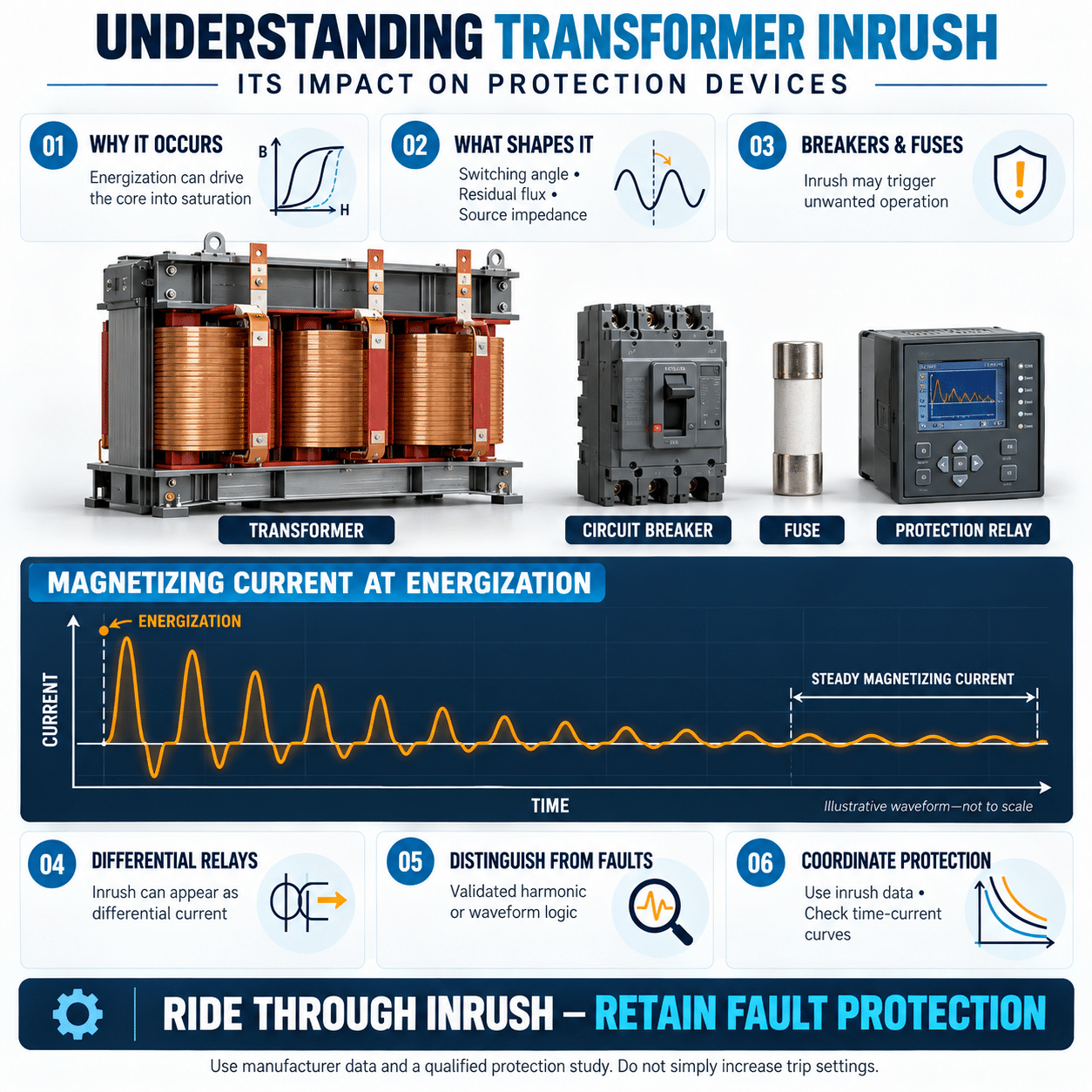
A transformer may draw only a small magnetizing current while operating with little or no load. At the instant it is energized, however, it can draw a current many times higher than its rated primary current.
This transformer inrush current is not necessarily a fault. It is a temporary electromagnetic condition created while magnetic flux is established in the transformer core.
To a circuit breaker, fuse or protective relay, inrush can resemble a short circuit. If protection is too sensitive, normal energization may disconnect the transformer. If protection is relaxed too far, genuine faults may not be cleared quickly enough.
Understanding transformer inrush therefore requires more than knowing that startup current is high. Engineers must understand what creates it, how it differs from a fault and how protection devices interpret the resulting waveform.
What happens when a transformer is energized?
A transformer operates by establishing alternating magnetic flux in its core.
The relationship among applied voltage, winding turns and core flux can be expressed as:
v(t) = N * d Φ(t) / dt
where:
- v(t) is the instantaneous winding voltage
- N is the number of winding turns
- Φ(t) is the magnetic flux
Rearranging the relationship shows that flux is determined by the time integral of applied voltage:
Φ(𝑡)=Φ(0)+1𝑁𝑡0𝑣(𝜏)𝑑𝜏 The initial flux, Φ(t), matters. The transformer core may retain residual magnetism from its previous energization.
When the transformer is switched on, the applied voltage begins driving flux from this initial condition. Depending on the switching point and residual flux direction, the first flux excursion may be much larger than the normal steady-state value.
If the flux exceeds the core’s linear operating region, the core saturates.
Why core saturation creates high current
Under normal conditions, the transformer core provides a high magnetizing inductance. Only a relatively small current is needed to establish the required flux.
When the core saturates, its effective magnetizing inductance falls sharply. The winding then offers much less opposition to current.
The current becomes limited mainly by:
- Winding resistance
- Transformer leakage reactance
- Source impedance
- Cable impedance
- Upstream transformer impedance
This produces the steep, asymmetrical waveform known as exciting inrush current.
The transformer does not need to be loaded for this to occur. A completely unloaded transformer can produce severe inrush because the event is associated with magnetizing the core, not supplying the secondary load.
Why closing at voltage zero can produce severe inrush
It may seem intuitive that closing a breaker when voltage is near zero would be the gentlest way to energize a transformer. For magnetic flux, the opposite can be true.
Because flux follows the integral of voltage, closing at a voltage zero crossing can produce the largest first-cycle flux excursion.
For a simplified sinusoidal voltage:
[
v(t) = V_m \sin(\omega t)
]
the corresponding steady-state flux is shifted by approximately 90 electrical degrees.
If the transformer is energized near a voltage peak, the required flux can begin closer to its natural steady-state trajectory. If it is energized near a voltage zero crossing, the flux may be driven far to one side before the voltage reverses.
Residual magnetism can make this effect more severe. If the residual flux is already in the same direction as the first applied flux excursion, the core may enter deep saturation.
This is one reason the inrush magnitude can vary greatly from one energization to the next, even when the same transformer is connected to the same source.
The role of residual flux
Residual flux is magnetism that remains in the core after the transformer is de-energized.
Its magnitude and polarity depend on:
- The point on the waveform when the transformer was disconnected
- Previous load conditions
- Core material
- Winding configuration
- Decaying system transients
- Breaker pole operation
- Prior faults
Suppose the normal peak operating flux is represented as 1.0 per unit. If residual flux is already 0.7 per unit in one direction and the initial voltage integral attempts to add another 2.0 per unit in the same direction, the theoretical flux demand can rise well beyond the core’s normal range.
The core cannot support that flux linearly. It saturates, causing the current to rise sharply.
Residual flux is not usually measured during routine energization, which is why transformer inrush is commonly treated as a range or envelope rather than one fixed current value.
What the inrush waveform looks like
Transformer inrush is different from normal load current.
Typical features include:
- Strong asymmetry
- A large first peak
- Significant DC offset
- Long intervals of relatively low current
- Current concentrated in one polarity
- Gradual decay over multiple cycles
- High harmonic content
- Different current in each phase
The first peak may be high, but the event is not defined by peak current alone. Protection response depends on the RMS current, duration, repetition and waveform.
In a three-phase transformer, each phase may behave differently because the breaker poles do not close at exactly the same electrical instant and the magnetic paths interact through the core.
Core construction also matters. Three-limb, five-limb and shell-form transformers can exhibit different phase relationships during energization.
How long does transformer inrush last?
The largest current usually occurs near initial energization, but the waveform can take much longer to settle fully.
The decay rate depends on:
- Transformer size
- Winding resistance
- Core losses
- Source impedance
- System X-to-R ratio
- Core saturation
- Residual flux
- Connected load
- Transformer design
A small control transformer may settle quickly. A large power transformer can produce a decaying transient that remains visible for seconds.
Protection must tolerate the complete inrush envelope, not only the first half-cycle.
Repeated attempts to energize a transformer after an upstream device trips can also produce different results because residual flux changes after every interruption.
Why inrush becomes a distribution-system problem
Transformer inrush affects more than the transformer itself.
It can cause:
- Instantaneous breaker trips
- Fuse operation
- Differential relay operation
- Contactor contact damage
- Source voltage sag
- Generator instability
- UPS transfer or current limiting
- Dropout of nearby contactors
- PLC or control-power resets
- Lighting disturbances
- Incorrect fault indications
- Failed automatic restoration sequences
The effect depends on the relationship among the transformer, source and protection system.
A stiff utility source may maintain voltage during the event. The same transformer connected to a standby generator or inverter-based source may cause a substantial voltage dip.
Impact on molded-case circuit breakers
A molded-case circuit breaker may use thermal-magnetic or electronic trip elements.
Long-time protection
The long-time function protects against sustained overload. Transformer inrush is normally too brief to operate this function unless the event is unusually long or repeated frequently.
Short-time protection
The short-time function responds to higher current with a deliberate delay. It can support coordination with downstream protection.
An inrush envelope that enters the short-time region may cause a trip if the current persists beyond the selected delay.
Instantaneous protection
The instantaneous function responds rapidly to high current. It is the function most likely to interpret the initial inrush peak as a short circuit.
The breaker must satisfy two opposing requirements:
- The instantaneous pickup must be high enough to ride through credible transformer inrush.
- The breaker must still clear low-impedance faults quickly enough to protect conductors and equipment.
Increasing the instantaneous setting is not automatically safe. The revised setting must be checked against minimum fault current, conductor withstand, transformer damage limits, arc-flash performance and upstream coordination.
Fuji Electric’s application guidance for transformer primary circuits compares the effective inrush current at a defined time with the breaker’s instantaneous trip characteristic. This illustrates why transformer protection must be selected from time-current behavior, not only rated current.
Why a breaker can trip with no secondary load
Technicians sometimes assume that an unloaded transformer should draw very little current and conclude that an instantaneous trip indicates a defective transformer.
During steady operation, the no-load current is small. During energization, the secondary load has little influence on the initial core-flux transient.
An unloaded transformer can therefore trip its primary breaker while a loaded transformer of the same rating may energize successfully on another attempt.
The relevant questions are:
- What was the point on the voltage waveform at closing?
- What residual flux remained?
- What was the source voltage?
- What was the actual inrush envelope?
- Where was the breaker’s magnetic or instantaneous pickup?
Impact on fuses
A fuse responds to the heating effect of current.
The energy associated with an event is often considered using (I^2t):
[
I^2t = \int i^2(t),dt
]
A high first peak may look severe, but a fuse may withstand it if the total energy is below its melting threshold. A lower current that persists longer can produce greater heating.
Transformer-primary fuses must be selected to:
- Carry rated load current
- Tolerate normal transformer inrush
- Withstand permissible short-duration overload
- Clear primary faults
- Coordinate with secondary protection
- Remain within conductor and transformer damage limits
A fast-acting fuse selected close to transformer full-load current may open during normal energization. A time-delay fuse may provide better inrush ride-through.
Increasing fuse size without a coordination study can leave the transformer or conductors inadequately protected.
Impact on differential protection
Large transformers may use differential protection.
Current transformers measure current entering and leaving the protected zone. Under normal conditions, the properly compensated values should balance.
An internal transformer fault creates differential current, so the relay operates.
Transformer energization also creates differential current because magnetizing inrush flows on the energized side without a corresponding secondary current. To a basic differential element, this can resemble an internal fault.
Modern transformer differential protection uses additional logic to distinguish inrush from faults.
Harmonic restraint and blocking
Transformer inrush typically contains substantial second-harmonic current because of its asymmetrical, saturated waveform.
Differential relays can compare the second-harmonic component with the fundamental component.
When the harmonic ratio indicates magnetizing inrush, the relay may:
- Restrain operation
- Block the differential element
- Increase the operating threshold
- Apply phase-specific logic
- Use cross-phase logic
Fuji Electric transformer protection systems have used second-harmonic suppression to prevent unwanted differential operation during energization.
Harmonic restraint must be applied carefully. Some internal faults can contain harmonics, while modern transformer cores may produce lower second-harmonic content during certain energization conditions.
Protection design may therefore combine harmonic analysis with:
- Waveform shape
- Current slope
- Flux estimation
- Zero-crossing behavior
- Differential-current magnitude
- Sequence components
- Time-based logic
- Other relay algorithms
The protection engineer should use the relay manufacturer’s application guidance and validate settings against the transformer design.
Current-transformer saturation
The primary current transformer, or CT, can saturate during severe inrush.
CT saturation can distort secondary current by:
- Clipping peaks
- Shifting phase
- Introducing false differential current
- Reducing measured magnitude
- Extending apparent DC offset
- Affecting harmonic calculations
CT selection should consider:
- Maximum inrush current
- Fault current
- DC offset
- Burden
- Lead resistance
- Accuracy class
- Knee-point voltage
- Remanence
- Relay requirements
A relay algorithm cannot interpret a waveform accurately if the CT reproduces it poorly.
Impact on contactors and switching devices
A contactor used to energize a transformer must withstand the making current.
High inrush can cause:
- Contact bounce
- Severe arcing
- Contact erosion
- Contact welding
- Reduced electrical life
- Pole-to-pole closing variation
The contactor should be selected for transformer or inductive-load duty, not solely from the transformer’s rated primary current.
Closing-pole timing can also influence phase inrush. A few milliseconds of difference between poles changes the electrical closing angle.
For large transformers, circuit breakers or dedicated controlled-switching equipment may be more appropriate than standard contactors.
Impact on generators
A generator typically has higher source impedance than the utility.
When a transformer is energized from a generator, inrush can produce:
- Deep voltage sag
- Frequency dip
- Automatic voltage regulator response
- Overexcitation
- Contactor dropout
- Relay operation
- Generator instability
- Failed transfer sequences
The voltage sag may reduce transformer inrush, but it can also affect every other load connected to the generator.
When several transformers are restored after an outage, energizing them simultaneously can compound the disturbance.
Sequential energization allows voltage and frequency to recover between events.
Impact on UPS and inverter-based sources
A UPS inverter has limited short-duration current capability. If transformer inrush exceeds that capability, the UPS may:
- Enter current limit
- Reduce output voltage
- Transfer to bypass
- Shut down
- Report an overload
- Fail to energize the transformer
A transformer that starts successfully from utility power may not start from a UPS inverter.
Review:
- UPS peak-current capability
- Duration of overload support
- Current-limit behavior
- Bypass availability
- Battery-mode performance
- Transformer inrush
- Downstream breaker coordination
If the transformer is downstream of a UPS, obtain compatibility guidance from both manufacturers.
Voltage and frequency matter
Transformer flux depends approximately on the ratio of voltage to frequency.
A higher voltage or lower frequency increases core flux.
This is particularly important when:
- Energizing from a generator
- Using a transformer rated for both 50 and 60 Hz
- Applying the wrong primary tap
- Operating during voltage regulation errors
- Restoring power during unstable frequency
A transformer connected to a voltage higher than the selected tap rating can experience increased inrush and higher steady-state magnetizing current.
A transformer designed for 50 and 60 Hz generally experiences more severe flux conditions at 50 Hz for the same applied voltage.
Protection selection should reflect the worst credible voltage and frequency combination.
How to analyze transformer inrush on a time-current curve
A time-current coordination study should include a transformer inrush envelope.
The study typically compares:
- Transformer full-load current
- Inrush envelope
- Primary breaker curve
- Primary fuse curve
- Secondary breaker curve
- Transformer thermal damage curve
- Conductor damage curve
- Available fault current
- Upstream protective-device curve
The inrush envelope should pass to the left or below the non-operating boundary of the selected primary protection.
At the same time:
- The breaker or fuse must remain below the transformer damage curve.
- The primary device should coordinate with downstream protection.
- Faults must be cleared within equipment and conductor limits.
- Instantaneous settings must remain sensitive to minimum fault current.
The inrush envelope should come from the transformer manufacturer where possible. Generic multiples of full-load current are useful only for early estimates.
An illustrative coordination example
Consider a transformer with a primary full-load current of 100 A.
Suppose the transformer manufacturer provides an inrush envelope that includes:
- 1,000 A at 0.01 second
- 600 A at 0.1 second
- 300 A at 1 second
These figures are illustrative, not universal.
A primary breaker with an instantaneous pickup below 1,000 A may trip during the first part of energization.
Raising the instantaneous pickup above 1,000 A may prevent that trip, but the engineer must then confirm:
- A primary fault produces enough current to operate the breaker.
- Conductors remain protected.
- Arc-flash results remain acceptable.
- Upstream and downstream devices coordinate.
- The transformer damage curve is not crossed.
- The breaker’s actual tolerance band clears the inrush envelope.
The correct answer may be a different breaker characteristic, not merely a higher current rating.
Why using a larger breaker is not the first solution
Oversizing the breaker can hide the inrush problem while weakening protection.
Potential consequences include:
- Reduced overload protection
- Slower fault clearing
- Poor downstream coordination
- Increased incident energy
- Conductor damage
- Transformer damage
- Code noncompliance
A better process is to determine whether the issue is caused by:
- Incorrect trip characteristic
- Incorrect instantaneous setting
- Abnormally severe inrush
- High applied voltage
- Low frequency
- Wrong transformer tap
- Simultaneous energization
- Weak source
- Transformer damage
- Incorrect CT or relay settings
Only then should the protection or energization method be changed.
Measuring transformer inrush
A standard clamp meter may not capture the event correctly.
Use an instrument with appropriate:
- Bandwidth
- Sampling rate
- Peak-current capability
- Inrush capture
- RMS calculation
- Data logging
- Voltage measurement
- Safety category
- Current-probe rating
Capture:
- All phase currents
- Phase-to-phase or phase-to-neutral voltages
- Breaker closing time
- First current peak
- RMS current over time
- Decay duration
- Voltage sag
- Harmonic content
- Relay event data
For medium-voltage systems, obtain data through properly rated CTs, protective relays or power-quality equipment. Do not attach portable instruments without an approved procedure.
The peak instantaneous current and the RMS value at a specific time serve different purposes. Breaker and fuse studies usually need a current-versus-time envelope.
Distinguishing inrush from an internal fault
A normal inrush event often has:
- Strong asymmetry
- High second-harmonic content
- Decaying magnitude
- Current primarily on the energized side
- A clear relationship to breaker closing
- No gas, pressure or temperature evidence of internal failure
An internal fault may show:
- Sustained high differential current
- Lower inrush-like harmonic content
- Negative-sequence current
- Sudden gas or pressure relay operation
- Abnormal winding resistance
- Insulation test failure
- Continued current until protection clears it
These are general tendencies, not definitive rules.
Never repeatedly re-energize a transformer simply because a trip is suspected to be inrush. Review relay targets, breaker records and transformer condition first.
Common causes of abnormal energization behavior
If a transformer that previously energized normally begins tripping protection, investigate:
- Incorrect tap position
- Higher source voltage
- Lower source frequency
- Changed breaker settings
- Replacement breaker with a different curve
- New relay firmware or settings
- CT wiring changes
- CT saturation
- Grounding changes
- Internal transformer damage
- Shorted turns
- Connected secondary fault
- Failed surge-protection equipment
- Simultaneous downstream load energization
- Failed precharge or control sequence
Do not assume every energization trip is normal inrush.
Methods for reducing transformer inrush
Controlled point-on-wave switching
Controlled switching closes each breaker pole at an electrical angle selected to reduce the initial flux offset.
The optimum closing angle depends on:
- Residual flux
- Winding configuration
- Core construction
- Pole operating time
- Breaker consistency
- Source voltage
Advanced systems may estimate residual flux and compensate the closing command for breaker travel time.
Controlled switching can be effective, but it requires accurate equipment and commissioning.
Preinsertion resistors
A resistor is inserted temporarily during energization to limit current. It is then bypassed after the magnetic transient has settled.
The resistor must be designed for:
- Energy dissipation
- Peak current
- Duty cycle
- Insulation
- Timing
- Failure mode
A failed bypass sequence can leave the resistor carrying continuous current, so monitoring and interlocking are required.
Reduced-voltage energization
Applying reduced voltage initially can reduce flux and inrush.
Possible methods include:
- Autotransformer starting
- Power-electronic voltage control
- Dedicated switching arrangements
The voltage must then rise in a controlled manner without causing renewed saturation.
Sequential energization
Where several transformers are present, energize them one at a time.
Sequence timing should allow:
- Inrush decay
- Source-voltage recovery
- Generator-frequency recovery
- Relay reset
- Stabilization of downstream control power
Fuji Electric has applied sequential breaker closing in power-system designs to reduce voltage fluctuation during large-transformer energization.
Energizing from the stronger source
When operationally permitted, energize the transformer from the source with greater short-circuit capacity, then transfer the system after the transient has passed.
This may be preferable to energizing directly from a generator or UPS inverter.
The transfer sequence must be designed and approved for the system.
Adjusting protection correctly
Breaker or relay settings can sometimes be changed to tolerate verified inrush.
Any change should be supported by:
- Transformer inrush data
- Fault study
- Coordination study
- Arc-flash study
- Equipment withstand
- Manufacturer guidance
- Applicable codes and standards
Protection settings should not be changed by trial and error.
Transformer inrush troubleshooting checklist
When a transformer trips protection during energization, ask:
- Which protective device operated?
- Which trip function operated?
- Did the event occur at breaker closing?
- Was the transformer loaded or unloaded?
- What were the source voltage and frequency?
- Was the correct transformer tap selected?
- What were the peak and RMS inrush currents?
- How long did the current take to decay?
- What voltage sag occurred?
- Did all three breaker poles close correctly?
- Did the differential relay identify harmonic restraint?
- Were any gas, pressure or temperature protections activated?
- Are CT ratios, polarity and burden correct?
- Has the breaker or relay setting changed?
- Is the source utility, generator or UPS?
- Were other transformers energized at the same time?
- Does the measured envelope match manufacturer data?
- Does the protection curve clear the inrush envelope?
- Does protection still clear the minimum fault safely?
- Has transformer condition been verified before re-energization?
Protection design checklist
Before finalizing transformer-primary protection, confirm:
- Transformer kVA and primary full-load current
- Voltage and frequency
- Winding and core configuration
- Manufacturer’s inrush envelope
- Maximum and minimum source strength
- Available short-circuit current
- Breaker long-time characteristic
- Breaker short-time characteristic
- Breaker instantaneous characteristic
- Fuse melting and clearing curves
- Transformer thermal and mechanical damage curves
- Primary and secondary conductor damage curves
- Differential relay inrush-restraint settings
- CT ratio, class, burden and saturation performance
- Generator and UPS energization capability
- Contactor or breaker making-current capability
- Selective-coordination requirements
- Arc-flash implications
- Energization sequence
- Mitigation required for weak-source operation
Transformer inrush must be treated as a protection-coordination problem
Transformer inrush is a normal electromagnetic event, but it can create serious operational problems when the source, transformer and protection system are not coordinated.
The current originates when the applied voltage, switching angle and residual core flux drive the transformer into saturation. The resulting waveform can resemble a fault, operate instantaneous protection, challenge differential relays and depress the source voltage.
The correct solution is not simply to install a larger breaker. Engineers must compare the credible inrush envelope with protective-device curves, transformer withstand limits, available fault current and source performance.
Fuji Electric provides molded-case circuit breakers, circuit protectors, power-monitoring equipment and protection technologies for electrical distribution systems. Applying these devices with transformer-specific inrush data supports reliable energization while preserving the fault protection the system requires.