
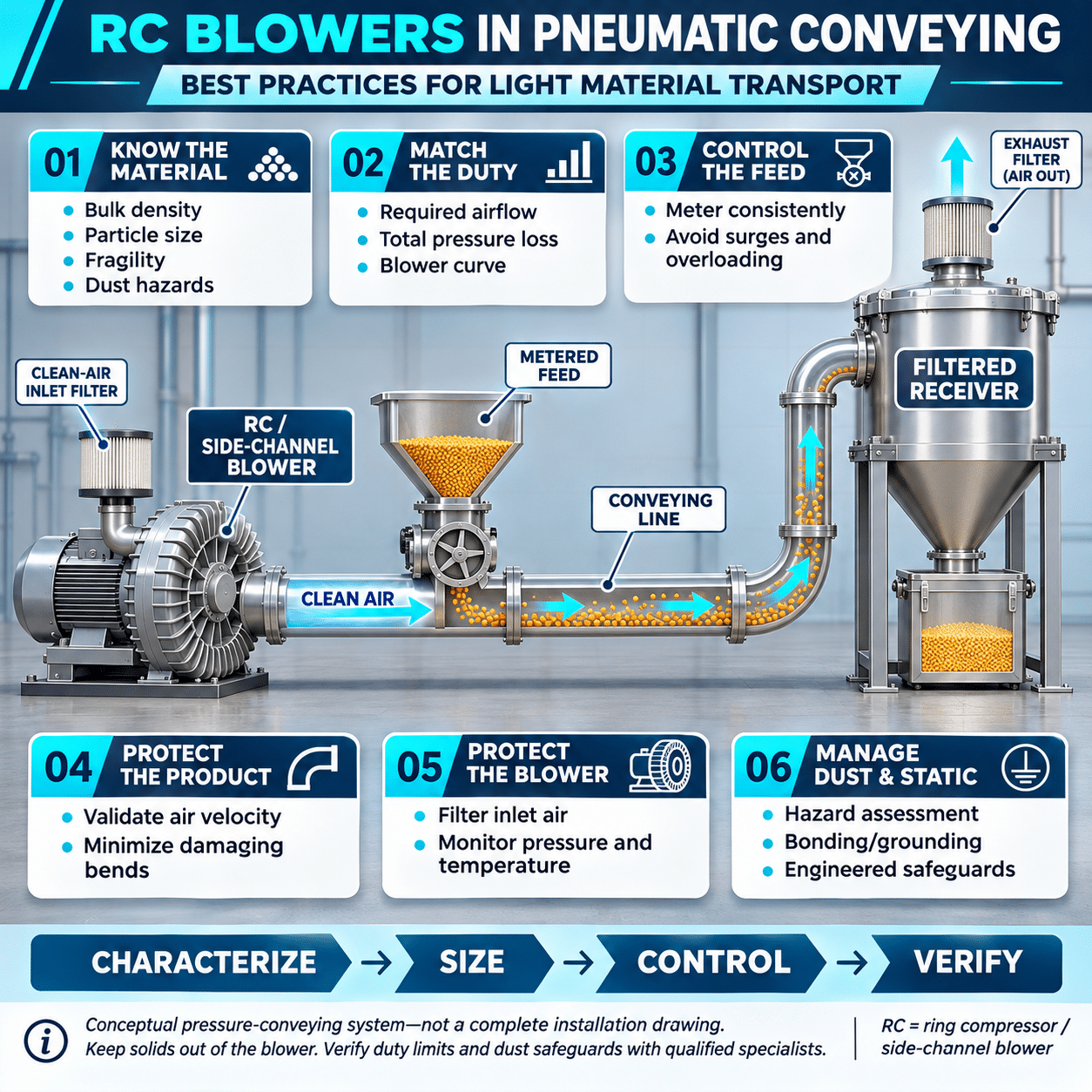
Pneumatic conveying uses moving air to transport bulk material through a pipeline. For lightweight materials and moderate conveying distances, a regenerative compressor blower, also known as an RC blower, ring compressor, or side-channel blower, can provide a compact and reliable source of pressure or vacuum.
Typical applications include transporting plastic pellets, small granules, paper trim, packaging scrap, lightweight food ingredients, fibers, and similar materials. Because the blower has no internal contact between the rotating impeller and stationary housing, it can supply clean, oil-free air with relatively low mechanical maintenance.
Successful conveying, however, depends on more than selecting a blower with enough maximum airflow. The system designer must match air velocity, pressure, pipeline geometry, material feed rate, filtration, temperature, and controls to the characteristics of the material.
An incorrectly sized system may plug frequently, damage the product, consume unnecessary energy, or overheat the blower. The following practices can help engineers and equipment manufacturers apply RC blowers effectively in light-material pneumatic conveying systems.
How an RC Blower Works
An RC blower uses a high-speed impeller with multiple blades rotating inside a ring-shaped housing. Air enters through the inlet, is accelerated by the impeller, and circulates repeatedly through the side channel before leaving through the discharge.
Each pass through the impeller adds energy to the air. This allows the blower to generate more pressure or vacuum than a conventional fan while delivering more airflow than many high-pressure compressor technologies.
RC blowers are generally characterized by:
- High-volume, low-pressure airflow
- Pressure or vacuum operation
- Oil-free air
- Direct-drive construction
- No contacting internal components
- Low routine maintenance
- Relatively smooth airflow
- Compact installation
The airflow is not constant as system resistance changes. As the required pressure or vacuum increases, delivered airflow generally decreases. Blower selection must therefore be based on the complete performance curve, not the maximum flow and maximum pressure values listed separately.
A blower cannot normally produce its maximum rated airflow and maximum rated pressure at the same operating point.
When RC Blowers Fit Pneumatic Conveying
RC blowers are well suited to dilute-phase conveying applications in which material is suspended in a relatively high-velocity air stream.
Potential applications include:
- Plastic pellets and regrind
- Bottle caps and small molded components
- Lightweight packaging materials
- Paper, film, and label trim
- Dry food particles
- Seeds and light agricultural products
- Textile fibers
- Small wood particles
- Foam pieces
- Empty containers
- Lightweight production scrap
They are most effective when the required pressure differential falls within the blower’s operating range and the material can be transported without an excessively high solids concentration.
A different blower or conveying technology may be required for:
- Long conveying distances
- High vertical lifts
- Dense-phase conveying
- Heavy or highly abrasive solids
- Very high material-transfer rates
- Sticky or cohesive powders
- Materials that compact easily
- Processes requiring high-pressure gas
- Applications with hazardous dust that require specialized equipment
The material should be tested when its behavior is uncertain. Two products with similar bulk density can convey very differently because of particle shape, moisture, friction, electrostatic properties, or tendency to interlock.
Choose Pressure or Vacuum Conveying
An RC blower can be used on either the pressure side or vacuum side of a conveying system.
Pressure Conveying
In a pressure system, the blower pushes air into the pipeline. Material is introduced downstream using a venturi, rotary airlock, screw feeder, or another feeding device.
Pressure conveying can be appropriate when:
- One pickup point feeds one or several destinations
- Material must travel a relatively long distance
- Positive pressure helps overcome pipeline resistance
- The discharge point can be separated from the conveying air
- Inward air leakage is undesirable
The feeder must introduce material without allowing excessive air to escape. A poorly sealed feeder can consume a large part of the blower’s capacity.
Vacuum Conveying
In a vacuum system, the blower pulls air through the pipeline. Material enters at one or more pickup points and is collected in a receiver before the air reaches the blower.
Vacuum conveying can be appropriate when:
- Material must be collected from several pickup points
- Dust containment is important
- Inward leakage is preferable to material escaping
- Pickup wands or flexible hoses are used
- The transport distance is moderate
The receiver, separator, and filter must remove material before air enters the blower. Product entering the blower can damage the impeller, create imbalance, plug internal passages, or present a safety hazard.
Characterize the Material Before Sizing
The first step is to document what will be transported.
Important properties include:
- Bulk density
- Particle size and distribution
- Particle shape
- Moisture content
- Abrasiveness
- Fragility
- Cohesiveness
- Static-charge tendency
- Maximum material temperature
- Hygroscopic behavior
- Combustibility
- Toxicity
- Food or pharmaceutical requirements
Bulk density affects the amount of material that must be moved for a given production rate. Particle size and shape influence pickup behavior and the velocity needed to keep the material suspended.
Fragile products may break if velocity is excessive or the pipeline contains sharp bends. Abrasive products can erode elbows, feeders, receivers, and piping. Hygroscopic products may absorb moisture from the conveying air and begin sticking to the pipe.
The design basis should also define whether the material is uniform. Recycled material, agricultural products, and production scrap may vary substantially from batch to batch.
Determine the Required Material-Transfer Rate
The system should be sized for the required mass flow, not merely the volume of the receiving hopper.
Document:
- Normal transfer rate
- Maximum transfer rate
- Batch size
- Required transfer time
- Duty cycle
- Number of pickup points
- Number of destinations
- Expected simultaneous transfers
- Future capacity requirements
The actual system should include reasonable margin for feeding variation, filter loading, and changes in material properties. Excessive margin, however, can lead to oversized piping and inefficient blower operation.
Establish the Conveying Velocity
The air velocity must be high enough to pick up the material and keep it moving through horizontal runs, vertical sections, and bends.
A small change in pipe diameter can significantly change velocity. If the pipe is too large, velocity may fall below the material’s suspension requirement and allow solids to settle. If the pipe is too small, pressure loss, product damage, noise, and wear may increase.
Required velocity depends on the material. Lightweight film trim may behave differently from plastic pellets, grain, or dense granules. Published guidelines can provide a starting point, but representative conveying tests offer better assurance for difficult materials.
Air density also changes with pressure, vacuum, temperature, and altitude. The designer must distinguish between standard cubic feet per minute and actual cubic feet per minute at the operating condition.
Calculate the Total Pressure Requirement
The RC blower must overcome all resistance in the system while delivering the required airflow.
Pressure losses may include:
- Straight pipe
- Elbows and bends
- Flexible hose
- Valves and diverters
- Pickup nozzles
- Venturis
- Feeders
- Vertical lift
- Filters
- Cyclones and receivers
- Discharge equipment
- Air leakage
- Acceleration of the material
- Friction between material and piping
The pressure loss of an empty pipeline is only part of the total. Introducing solids increases the required pressure differential, sometimes substantially.
The system design should evaluate:
- Clean, empty-pipe operation
- Normal material loading
- Maximum material loading
- Partially loaded filters
- The most restrictive conveying route
- Startup with material in the line
- Credible upset conditions
The blower’s duty point should be located on its published pressure-flow or vacuum-flow curve. Select a model that provides the required airflow at the calculated pressure, with reasonable operating margin.
Do not select the blower by matching the calculated pressure to the model’s maximum pressure rating. Operating continuously at the extreme end of the curve can reduce airflow, increase temperature, and overload the motor.
Minimize Pipeline Resistance
A well-designed pipeline reduces the pressure required from the blower and improves conveying reliability.
Best practices include:
- Keep the route as short as practical.
- Minimize the number of elbows.
- Use long-radius bends when material behavior permits.
- Avoid unnecessary changes in pipe diameter.
- Eliminate abrupt restrictions.
- Support piping to prevent sagging.
- Keep flexible hose sections short.
- Use smooth internal joints.
- Avoid pockets where material can collect.
- Provide access for inspection and cleanout.
- Use wear-resistant bends for abrasive material.
Each elbow changes the direction of both the air and solids. The particles may strike the outside wall of the bend, increasing pressure loss, product damage, and pipe wear.
Back-to-back elbows are particularly challenging because the flow has little opportunity to stabilize between direction changes.
Feed Material at a Controlled Rate
A pneumatic conveying system can move only the amount of material that the available airflow can carry. Feeding material too quickly can cause pressure to rise, velocity to fall, and the pipeline to plug.
Common feeding devices include:
- Rotary airlocks
- Screw feeders
- Venturi eductors
- Slide gates
- Vibratory feeders
- Pickup wands
- Metering valves
The feeding method should match the material and system pressure.
Rotary airlocks can meter solids while limiting air leakage, but rotor clearance and pocket design must suit the particle size. Fragile material may be sheared between the rotor and housing.
Venturi systems have no moving parts in the material path, but they can require significant airflow and pressure. Their performance should be included in the blower sizing calculation.
A controlled feeder can be connected to pressure, airflow, or motor-current feedback. If system resistance begins to rise, the controller can reduce the material feed rate before the line becomes blocked.
Protect the Blower With Filtration
Clean inlet air is essential to RC blower life. Dust accumulation on the impeller or inside the side channel can reduce performance and create imbalance.
In pressure conveying, install an inlet filter sized for the blower’s airflow. The filter should create minimal pressure drop when clean and should not become excessively restrictive as it collects dust.
In vacuum conveying, the material receiver and final filter are especially important. The system may use:
- A cyclone separator
- Filter bags
- Cartridge filters
- A filter receiver
- A secondary safety filter
- An automatic filter-cleaning system
A differential pressure indicator or transmitter can show when the filter needs cleaning. Waiting until airflow visibly declines may allow the blower to operate at excessive vacuum and temperature.
Filters should be accessible for inspection and replacement. Maintenance personnel should not need to disassemble the entire receiver to reach a routine service item.
Maintain Minimum Airflow
An RC blower uses the air passing through it to remove heat. Restricting the inlet or discharge reduces airflow while the blower continues adding energy to the air.
A deadheaded or severely restricted blower can overheat rapidly.
The system should include the protective devices recommended for the selected model, which may include:
- Pressure relief valve
- Vacuum relief valve
- Minimum-flow bypass
- Temperature switch
- Motor-overload protection
- Pressure or vacuum switch
- Inlet-filter restriction indicator
A relief valve protects the blower only when it is correctly sized and adjusted. The valve setpoint should remain below the blower’s allowable continuous pressure or vacuum while staying above the normal operating range.
The discharge or suction path of a relief device should be arranged safely. In dusty or sanitary environments, releasing or drawing unfiltered air may be unacceptable.
Account for Temperature Rise
Compression increases air temperature. The amount of temperature rise depends on pressure ratio, airflow, blower efficiency, and operating conditions.
Hot conveying air can affect:
- Heat-sensitive plastics
- Food products
- Moisture content
- Flexible hose
- Filter media
- Seals and gaskets
- Product quality
- Blower motor temperature
A blower operating at higher pressure and lower flow generally experiences a greater temperature rise. High ambient temperature compounds the problem.
The design may require:
- A larger blower operating at a less restrictive duty point
- Improved room ventilation
- An aftercooler
- Insulated or guarded piping
- High-temperature hose and filter materials
- Temperature monitoring
- A shutdown or alarm setpoint
The blower should not draw its own hot discharge air back into the inlet. Keep the intake away from poorly ventilated enclosures and hot process equipment.
Consider Variable-Speed Control
A variable frequency drive can adjust the speed of a compatible three-phase RC blower to match process demand.
Potential benefits include:
- Reduced airflow during lower production rates
- Controlled startup
- Improved material-feed coordination
- Lower noise at reduced speed
- Reduced energy use when full capacity is unnecessary
- Pressure or vacuum regulation
- Multiple operating recipes
Variable speed must remain within the blower manufacturer’s approved operating limits. Reducing speed too far can lower conveying velocity below the point required to keep material suspended.
When controlling by pressure or vacuum alone, remember that a stable pressure reading does not necessarily prove adequate transport velocity. Control logic may need to enforce a minimum blower speed or minimum measured airflow.
The drive should be sized from the motor nameplate current and application requirements. Motor cooling, frequency range, overload capacity, and electrical compatibility must be confirmed.
Monitor the Right Variables
A few well-selected measurements can help operators identify problems before the system plugs or the blower overheats.
Useful measurements include:
- Blower inlet vacuum
- Blower discharge pressure
- Differential pressure across filters
- Airflow
- Discharge-air temperature
- Motor current
- Motor winding temperature
- Blower vibration
- Material-feed rate
- Receiver level
- Rotary-airlock status
System trends are often more valuable than a single alarm threshold.
For example:
- Rising filter differential pressure indicates filter loading.
- Rising blower pressure with falling material rate may indicate a developing restriction.
- Falling pressure and rising motor speed may suggest a leak.
- Increasing vibration may indicate material buildup or impeller damage.
- High motor current may indicate operation outside the approved curve.
- Repeated receiver high-level alarms may indicate a discharge problem.
The controls should stop or reduce material feeding before stopping the blower. Allowing the blower to run briefly after the feeder stops can help clear material from the pipeline.
Use a Proper Startup Sequence
A typical conveying sequence should establish airflow before material enters the line.
A basic pressure-conveying sequence may be:
- Confirm that the receiving destination is ready.
- Position the required diverter valves.
- Start the blower.
- Verify adequate pressure or airflow.
- Start the material feeder.
- Monitor the conveying condition.
- Stop the feeder when the transfer is complete.
- Continue airflow long enough to clear the line.
- Stop the blower.
A vacuum-conveying sequence may also include receiver isolation, filter cleaning, and discharge-valve operation.
Starting the material feeder before establishing airflow can create a plug at the pickup point. Stopping the blower before clearing the line can leave material in horizontal sections and make the next startup more difficult.
Manage Noise
RC blowers can generate sound from the motor, impeller, inlet, discharge, and high-velocity airflow.
Noise-control measures may include:
- Inlet silencer
- Discharge silencer
- Flexible connectors
- Vibration-isolated mounting
- Acoustic enclosure
- Lower operating speed
- Reduced air velocity
- Proper pipe supports
- Locating the blower away from occupied work areas
An acoustic enclosure must not restrict blower cooling. It should provide adequate ventilation and access for maintenance.
Flexible connectors can limit vibration transmission, but they should not be used to correct misaligned piping or support pipe weight.
Address Dust and Material Hazards
Some powders and lightweight materials can create combustible dust clouds. Static electricity generated by moving particles can provide an ignition source.
A hazard analysis should consider:
- Combustibility of the material
- Minimum ignition energy
- Dust concentration
- Static-charge generation
- Grounding and bonding
- Equipment temperature
- Potential ignition sources
- Explosion venting or suppression
- Isolation between connected equipment
- Area electrical classification
- Safe disposal of collected dust
A standard RC blower should not be assumed suitable for a classified hazardous location or combustible-dust service. The motor, blower construction, accessories, filters, controls, and complete conveying system must meet the requirements established by the hazard assessment and applicable codes.
Food, pharmaceutical, and sensitive-product applications may also require sanitary materials, validated cleaning procedures, and protection against contamination. Oil-free airflow does not automatically make a blower or conveying system sanitary.
Select the Correct RC Blower Configuration
Single-stage RC blowers generally provide higher airflow at moderate pressure or vacuum. They are often suitable for light-material pneumatic transport with modest system resistance.
Two-stage models route the air through a second compression stage. They can provide greater pressure or vacuum but may deliver less airflow than a comparably sized single-stage configuration.
The choice should be based on the calculated duty point.
A single-stage blower may be appropriate when the system has:
- Short or moderate conveying distance
- Lightweight material
- Limited vertical lift
- Relatively low solids loading
- Low to moderate pressure requirement
A two-stage blower may be considered when the system has:
- Greater pipeline resistance
- Higher vertical lift
- More restrictive filtration
- A higher required vacuum
- A duty point beyond the practical range of a single-stage unit
A two-stage blower should not be selected simply because more pressure appears safer. If the application primarily requires airflow, a higher-pressure model may operate less efficiently or provide insufficient velocity.
Fuji Electric offers single-stage and two-stage ring compressor configurations across a range of airflow, pressure, vacuum, motor-power, and voltage ratings. The appropriate model should be selected from its full performance curve at the actual system duty point.
Avoid Common Selection Mistakes
Selecting by Maximum Airflow
Maximum airflow is normally specified at little or no pressure differential. The system will receive less airflow after pipeline, filter, and material losses are applied.
Selecting by Maximum Pressure
Maximum pressure occurs near the low-flow end of the curve. It is not the recommended continuous duty point for every application.
Ignoring the Material Load
An empty-pipe test may look successful even though the system cannot transport the required quantity of material.
Oversizing the Pipe
A larger pipe reduces air friction but may lower velocity enough to let solids settle.
Undersizing the Pipe
A smaller pipe increases velocity but can create high pressure loss, noise, abrasion, and product damage.
Omitting a Relief Valve
A blocked pipeline, closed valve, or dirty filter can move the blower into an unsafe operating condition.
Allowing Material Into the Blower
Product carryover can damage the impeller and create an unsafe condition. Vacuum systems require effective separation and final filtration.
Ignoring Air Leakage
Leaks at rotary valves, receiver lids, flexible connections, and pipe joints reduce the air available for conveying.
Running the Blower Without Clearing the Line
Improper stopping sequences leave material in the pipe and increase the likelihood of a plug at the next startup.
RC Blower Selection Checklist
Before selecting an RC blower, document:
- Material type
- Bulk density
- Particle size and shape
- Moisture and temperature
- Abrasiveness and fragility
- Combustibility
- Required material-transfer rate
- Pressure or vacuum conveying
- Pipe inside diameter
- Horizontal pipe length
- Vertical lift
- Number and type of bends
- Flexible-hose length
- Feeder type
- Receiver and separator losses
- Clean and dirty filter pressure drop
- Air leakage allowance
- Required conveying velocity
- Total system pressure or vacuum
- Ambient temperature and altitude
- Electrical voltage and phase
- Duty cycle
- Required controls and monitoring
- Noise limits
- Applicable sanitary or hazardous-location requirements
Keep the System Operating Efficiently
Routine inspection should include:
- Cleaning or replacing inlet filters
- Checking receiver and final filters
- Testing pressure and vacuum relief valves
- Inspecting piping for leaks
- Checking flexible connectors
- Examining elbows for wear
- Verifying blower motor current
- Reviewing temperature and pressure trends
- Checking fasteners and mounting hardware
- Inspecting the impeller if contamination or vibration is suspected
- Confirming that material feeders operate consistently
- Testing alarms and interlocks
Operators should also record the normal pressure, vacuum, current, airflow, and temperature when the system is clean and operating correctly. These baseline values make future troubleshooting much easier.
Treat the Blower and Conveying Line as One System
An RC blower is the air source, but it cannot compensate for every weakness in the conveying-system design. Reliable transport depends on the relationship among the blower, pipe diameter, route, feeder, receiver, filter, material properties, and control sequence.
The most successful light-material conveying systems use enough air velocity to keep the product moving, but not so much that they waste energy or damage the material. They also provide adequate pressure margin without forcing the blower to operate near its maximum limit.
By selecting a Fuji Electric RC blower from the complete performance curve and coordinating it with the entire conveying process, equipment designers can achieve clean, reliable, and low-maintenance transport of lightweight materials.