
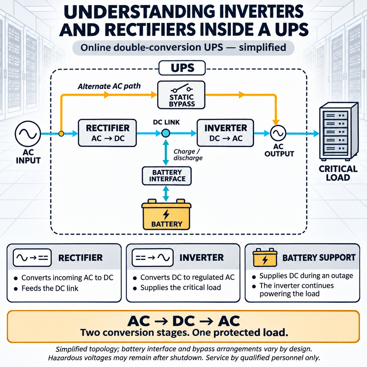
An uninterruptible power supply, or UPS, protects critical equipment when utility power becomes unstable or unavailable. Batteries receive much of the attention in UPS discussions, but batteries are only one part of the system.
In an online double-conversion UPS, the rectifier and inverter perform most of the continuous power conversion. The rectifier converts incoming alternating current into direct current. The inverter converts that direct current back into controlled alternating current for the critical load.
Between them is a DC link that connects the conversion stages with the battery or another energy-storage system. Together, these components determine how effectively the UPS regulates voltage, handles load changes, interacts with a generator, limits harmonics, and maintains power during an outage.
Understanding the functions of the rectifier and inverter makes it easier to evaluate UPS specifications and identify which performance characteristics matter for a particular application.
The Basic Power Path
The normal power path through an online double-conversion UPS can be simplified as:
[
\text{Utility AC} \rightarrow \text{Rectifier} \rightarrow \text{DC Link} \rightarrow \text{Inverter} \rightarrow \text{Critical AC Load}
]
The battery connects to the DC side of the system, either directly or through a DC-to-DC converter, depending on the UPS architecture.
During normal operation:
- Utility AC enters the rectifier.
- The rectifier converts AC to regulated DC.
- The DC link supplies the inverter.
- The inverter creates regulated AC for the load.
- The battery charger maintains the battery at the required state of charge.
When utility power fails:
- The rectifier can no longer obtain energy from the input source.
- The battery supplies energy to the DC link.
- The inverter continues supplying the critical load.
- No normal transfer from the rectifier to the battery is required at the UPS output because the inverter was already operating.
This continuous conversion is why the architecture is called online double conversion. Power is normally converted twice, first from AC to DC and then from DC to AC.
What Does the Rectifier Do?
A rectifier converts alternating current into direct current. In a UPS, its role is more sophisticated than that basic definition suggests.
The rectifier must:
- Draw power from the utility or generator
- Convert input AC to regulated DC
- Supply the inverter’s real-power demand
- Support battery charging
- Control input current
- Limit harmonic distortion
- Maintain a high input power factor
- Respond to changes in load
- Operate over the specified input-voltage and frequency range
The rectifier is the part of the UPS that the upstream electrical system sees as a load. Its design affects transformers, generators, switchgear, conductors, and upstream protective devices.
Basic Rectifier Technologies
Several rectifier technologies have been used in UPS systems.
Diode Rectifiers
A diode bridge is a simple and robust method of converting AC into DC. Current flows through the diodes according to the instantaneous input voltage.
Diode rectifiers are reliable, but a basic design can draw current in short pulses rather than as a smooth sine wave. This can produce input-current harmonics and may require passive filters or other corrective measures.
A diode rectifier by itself also provides limited control over the input-current waveform and DC voltage.
Thyristor or SCR Rectifiers
Silicon-controlled rectifiers, commonly called SCRs or thyristors, allow the firing point of each device to be controlled. This gives the rectifier more control over DC output and battery charging than an uncontrolled diode bridge.
SCR rectifiers have been used extensively in industrial UPS systems, particularly where rugged construction and high power are important.
Potential design considerations include:
- Input-current harmonics
- Input power factor
- Generator compatibility
- Larger input filters
- Greater upstream infrastructure requirements
Performance depends on the complete rectifier design, loading, and filtering arrangement.
IGBT Active Rectifiers
Modern UPS systems often use insulated-gate bipolar transistors, or IGBTs, in a pulse-width-modulated active rectifier.
Instead of allowing the AC waveform to determine when current flows, the controller switches the IGBTs rapidly to shape the input current. This allows the rectifier to draw current in a waveform that more closely follows the input voltage.
An active IGBT rectifier can provide:
- High input power factor
- Low input-current harmonic distortion
- Controlled DC-link voltage
- Wide input-voltage tolerance
- Controlled startup
- Improved generator compatibility
- Reduced dependence on large passive harmonic filters
The switching strategy, semiconductor technology, magnetic components, and control software all influence the final performance.
Input Power Factor
Input power factor describes how effectively the UPS uses current drawn from the source.
A useful power relationship for a three-phase system is:
[
P = \sqrt{3}VI\text{PF}
]
Where:
- (P) is real power
- (V) is line-to-line voltage
- (I) is line current
- (\text{PF}) is power factor
For a given real-power demand, a lower power factor requires more input current. Higher current can increase conductor losses, voltage drop, generator loading, and required equipment capacity.
A modern active rectifier can maintain an input power factor close to unity across a useful operating range. Performance should still be reviewed at partial load because data centers and other redundant facilities may operate individual UPS modules below full capacity.
Input-Current Harmonics
A nonlinear rectifier can distort the input-current waveform. This distortion is commonly expressed as total harmonic distortion of current, or THDi.
High harmonic current can contribute to:
- Additional transformer heating
- Generator voltage distortion
- Increased conductor losses
- Resonance with capacitors
- Higher neutral current in some systems
- Interference with other equipment
- Reduced usable source capacity
An active rectifier can control the current waveform and reduce THDi. The published value should be reviewed at the expected load level and under the specified input conditions.
A low THDi value at full load does not necessarily guarantee the same result at 10 or 25 percent load.
Rectifier Walk-In
When a UPS returns to normal operation after running on battery, the rectifier must resume supplying both the inverter and the battery charger. Applying the full load abruptly could create a sudden demand on the utility or generator.
A power walk-in function gradually increases rectifier input power. This gives the source time to accept the load and can reduce:
- Generator frequency disturbance
- Sudden transformer loading
- Input-current steps
- Interaction with other large loads
Generator-backed UPS systems should be evaluated using the complete sequence:
- Utility power fails.
- The UPS operates from stored energy.
- The generator starts.
- The generator voltage and frequency stabilize.
- The UPS accepts the source.
- The rectifier gradually assumes load.
- Battery recharging begins according to the configured limits.
Rectifier walk-in time and battery recharge current should be coordinated with generator capacity and other emergency loads.
What Does the Inverter Do?
An inverter converts DC into AC. In an online UPS, it continuously supplies the critical output bus during normal double-conversion operation.
The inverter must create an output voltage with the correct:
- Magnitude
- Frequency
- Phase sequence
- Waveform
- Phase balance
- Transient response
It must also support a variety of loads, including servers, storage equipment, network devices, medical systems, industrial controls, variable frequency drives, and other power electronic equipment.
The inverter is the part of the UPS that the critical equipment sees as its power source.
How the Inverter Creates AC
The battery and DC link provide direct voltage with fixed polarity. To create AC, the inverter switches semiconductor devices in a controlled pattern.
Pulse-width modulation, or PWM, is commonly used. The inverter turns its power semiconductors on and off at high frequency, creating a series of voltage pulses. An output filter smooths these pulses into an AC waveform suitable for the load.
The controller continuously measures output voltage and current. It adjusts the switching pattern to maintain the required waveform as the load changes.
This closed-loop control enables the inverter to correct for:
- Utility voltage variations
- Load steps
- Phase imbalance
- Nonlinear load current
- Battery-voltage changes
- Frequency variations at the input
IGBTs in UPS Inverters
IGBTs combine a voltage-controlled gate with the current-handling capability required for high-power conversion. They have been widely used in UPS inverters because they can switch rapidly while supporting substantial voltage and current.
An IGBT has two important operating loss categories.
Conduction loss occurs while current flows through the device.
Switching loss occurs during transitions between the on and off states.
Higher switching frequency can improve waveform control and reduce the size of some magnetic and filter components, but it may increase switching loss. UPS design therefore requires a balance among efficiency, waveform quality, component size, thermal performance, and reliability.
Two-Level and Three-Level Conversion
A conventional two-level inverter switches each output phase between the positive and negative portions of the DC bus.
A three-level converter adds an intermediate voltage level. This reduces the voltage step applied during each switching event.
Potential advantages include:
- Lower switching stress
- Lower output waveform distortion
- Smaller filter requirements
- Reduced switching loss
- Improved efficiency
- Lower electromagnetic noise
The actual benefit depends on the circuit topology and semiconductor implementation.
Fuji Electric applies an advanced three-level topology in its UPS power conversion stages. Its AT-NPC design uses reverse-blocking IGBT technology and silicon carbide diodes in selected functions to reduce conversion losses while maintaining the performance required by critical loads.
The DC Link Connects the Two Stages
The DC link is the electrical connection between the rectifier, inverter, and energy-storage system.
It typically includes:
- Positive and negative DC conductors
- DC-link capacitors
- Protective devices
- Voltage and current sensors
- Battery connections
- A DC-to-DC converter in some designs
The DC-link capacitors help stabilize voltage and supply short bursts of energy during rapid changes in inverter demand. They also reduce ripple between the switching converter stages.
The rectifier and inverter do not always exchange exactly the same instantaneous power. The DC link absorbs and releases energy over short intervals to keep the system stable.
How the Battery Connects to the DC Link
UPS architectures differ in how the battery is connected.
Direct Battery Connection
In some designs, the battery connects directly to the DC bus through a battery disconnect and protective devices. The battery voltage therefore varies within the DC range accepted by the inverter.
DC-to-DC Converter Connection
Other designs place a bidirectional DC-to-DC converter between the battery and DC link.
This converter can:
- Regulate charging current
- Control battery discharge
- Allow a battery voltage different from the main DC-link voltage
- Support different energy-storage technologies
- Stabilize the DC link during battery operation
- Improve control over battery testing and protection
The term rectifier is sometimes used broadly to describe the entire input conversion and charging section. In a modern UPS, however, the rectifier, DC-to-DC stage, and battery charger may be separate functional blocks.
What Happens During a Utility Outage?
In normal online operation, the inverter is already supplying the load. When utility input disappears, the DC-link voltage begins to fall, and the battery system immediately supplies energy to the DC bus.
The power path becomes:
[
\text{Battery} \rightarrow \text{DC Link} \rightarrow \text{Inverter} \rightarrow \text{Critical Load}
]
The output does not need to be transferred from the utility to a newly started inverter. The inverter remains the source before, during, and after the event.
This provides continuous output through many input disturbances, subject to the UPS operating limits and available stored energy.
The inverter must adapt as battery voltage changes during discharge. When the battery reaches its minimum allowable voltage or stored energy is exhausted, the UPS can no longer support the load unless another source has become available.
What Happens When Utility Power Returns?
When the input source returns and remains within the UPS acceptance limits:
- The rectifier synchronizes with and accepts the source.
- Input power increases according to the configured walk-in function.
- The rectifier resumes supplying the inverter.
- Battery discharge stops.
- The charger begins restoring battery capacity.
- The inverter continues supplying the load throughout the sequence.
Battery charging should be controlled so it does not overload the input source. If the generator has limited spare capacity, the UPS may need a reduced recharge-current setting.
The Static Bypass Path
A double-conversion UPS also includes a bypass path. The static bypass connects an alternate AC source directly to the critical output using solid-state switching devices.
The bypass may support the load when:
- The inverter is overloaded beyond its short-term capability
- An internal UPS fault occurs
- The system is transferred intentionally
- The load produces a fault current the inverter cannot sustain
- The UPS operates in a high-efficiency mode
For a transfer to occur without unacceptable disturbance, the inverter is normally synchronized with the bypass source when that source is within the allowed voltage, frequency, and phase limits.
The bypass does not provide the same power conditioning as the inverter. When the load is on bypass, input voltage and frequency disturbances may pass more directly to the critical equipment.
Inverter Overload Capability
Critical loads do not always draw steady current. Transformers, motors, power supplies, and capacitive loads can produce short-duration inrush or overload conditions.
Inverter specifications may include capabilities such as:
- Continuous full-load current
- Short-duration overload
- Peak or crest current
- Unbalanced load support
- Leading and lagging power-factor range
- Short-circuit current
The time associated with an overload rating is important. An inverter may support 125 percent load for several minutes but a larger overload for only seconds or cycles.
If the load demand exceeds inverter capability and bypass is available, the UPS may transfer the load. If bypass is unavailable or outside tolerance, the inverter may current-limit or shut down according to its protection logic.
Short-Circuit Performance
An inverter is a semiconductor-controlled source. It cannot generally supply the same magnitude of fault current as a utility transformer.
During an output short circuit, the inverter limits current to protect its semiconductor devices. This has important implications for:
- Downstream breaker operation
- Fuse clearing
- Protective coordination
- Selective isolation
- Arc-flash calculations
- Static bypass transfer
The system designer should evaluate fault clearing in each operating mode:
- Inverter operation
- Battery operation
- Static bypass operation
- Maintenance bypass operation
A downstream protective device that clears quickly on utility power may behave differently when supplied by a current-limited inverter.
Load Power Factor
UPS capacity is commonly expressed in both kilovolt-amperes and kilowatts.
Apparent power is:
[
S = VI
]
For a three-phase system:
[
S = \sqrt{3}VI
]
Real power is:
[
P = S \times \text{PF}
]
A UPS rated at 500 kVA and 500 kW has a unity output power-factor rating. However, the connected load may operate at a leading or lagging power factor.
The inverter must handle the required current even when real power is below the kilowatt rating. A UPS should therefore be checked against both:
- Total kW demand
- Total kVA demand
- Load power-factor range
- Harmonic current
- Peak current
Modern IT power supplies often have power-factor correction, but actual facility loads can still include leading, lagging, and nonlinear characteristics.
Nonlinear Loads and Crest Factor
Many electronic loads draw current in pulses rather than as a smooth sine wave. These current pulses can distort the UPS output voltage if the inverter and output filter are not designed to handle them.
Review:
- Output-voltage total harmonic distortion
- Performance with nonlinear loads
- Crest-factor capability
- Neutral-current capability in four-wire systems
- Voltage regulation under unbalanced load
- Response to rapid load changes
A low output-voltage distortion specification under a linear load does not fully describe performance with modern electronic equipment. The nonlinear-load specification is often more relevant.
Transient Response
A large block of load may be added or removed suddenly. Examples include:
- A server cluster starting
- A cooling unit cycling
- A transformer energizing
- A redundant power path transferring
- A large load bank connecting during a test
The inverter controller must respond quickly enough to keep output voltage within acceptable limits.
Transient specifications should describe:
- Magnitude of the load step
- Resulting voltage deviation
- Recovery time
- Test power factor
- Whether the battery was used
- Whether the bypass assisted
- Balance or imbalance of the load
A high-quality inverter can support large load steps while maintaining a tightly regulated output.
Rectifier and Inverter Efficiency
Both conversion stages produce losses.
The overall double-conversion efficiency can be approximated as:
[
\eta_{\text{UPS}} \approx \eta_{\text{rectifier}} \times \eta_{\text{inverter}} \times \eta_{\text{other}}
]
Where (\eta_{\text{other}}) accounts for controls, fans, magnetics, and auxiliary systems.
UPS power loss can be estimated from output power and efficiency:
[
P_{\text{loss}} = P_{\text{out}}\left(\frac{1}{\eta}-1\right)
]
For a 1,000 kW output at 97 percent efficiency:
[
P_{\text{loss}} = 1{,}000\left(\frac{1}{0.97}-1\right)
]
[
P_{\text{loss}} \approx 30.9\ \text{kW}
]
That heat must be removed continuously by the facility cooling system. Conversion efficiency therefore affects both electrical energy use and cooling demand.
Efficiency should be evaluated across the expected load profile, not only at the published peak. Redundant UPS systems may operate individual modules at relatively low loading.
High-Efficiency Operating Modes
Some UPS systems provide a high-efficiency mode in which the critical load is normally supplied through the bypass path rather than through both power-conversion stages.
In this mode:
- The rectifier and inverter may not carry the full load continuously.
- Conversion losses are reduced.
- The UPS monitors the bypass source.
- The inverter assumes the load when the source moves outside permitted limits.
This mode can achieve higher efficiency, but it does not provide the same continuous double-conversion conditioning.
Evaluate:
- Transfer time
- Load sensitivity
- Utility power quality
- Voltage and frequency limits
- Surge exposure
- Harmonic behavior
- Synchronization
- Operating-mode reliability
- Facility risk tolerance
High-efficiency mode is an operating choice, not merely a better efficiency number.
Semiconductor Technology and UPS Performance
Power semiconductor characteristics influence rectifier and inverter performance.
Important characteristics include:
- Blocking voltage
- Current capacity
- Conduction voltage drop
- Switching speed
- Reverse-recovery behavior
- Thermal resistance
- Short-circuit tolerance
- Reliability under repeated thermal cycling
Silicon IGBTs remain widely used because they combine established reliability with high power capability. Silicon carbide devices can reduce selected switching and recovery losses, particularly when applied where their characteristics provide the greatest system benefit.
Fuji Electric combines semiconductor development with UPS system engineering. In the UPS7400WX-T3U, Fuji Electric uses its AT-NPC three-level topology, reverse-blocking IGBT technology in the rectifier and inverter, and silicon carbide diodes in the rectifier.
This coordinated design supports high efficiency while maintaining input-current quality, regulated output, and overload capability.
Thermal Management
Conversion losses become heat inside the UPS. Rectifier and inverter power modules must remain within their allowable junction temperatures.
The cooling system may include:
- Heat sinks
- Forced-air fans
- Temperature sensors
- Airflow monitoring
- Redundant fans
- Thermal alarms
- Power derating
- Controlled shutdown
Temperature affects semiconductor life, capacitor life, insulation, and fan reliability. Blocked filters, failed fans, high room temperature, or inadequate clearance can reduce the UPS’s operating margin.
Maintenance should include inspection of:
- Fans
- Air passages
- Heat sinks
- Temperature history
- Capacitors
- Power connections
- Signs of discoloration
- Dust accumulation
- Alarm logs
A high-efficiency converter produces less heat, but it still requires suitable environmental control.
Rectifier and Inverter Redundancy
Modular UPS systems can divide conversion capacity among multiple power modules. Each module may contain its own rectifier, inverter, controls, and cooling components.
An N+1 configuration provides one more module than the load requires. If one module becomes unavailable, the remaining modules can continue supporting the load, provided they have sufficient capacity.
Redundancy planning should evaluate:
- Rectifier-module redundancy
- Inverter-module redundancy
- Control-system redundancy
- Fan redundancy
- Static-bypass capacity
- Battery arrangement
- Common input and output components
- Maintenance isolation
- Failure domains
- Load sharing among modules
A modular label alone does not prove that every internal component is redundant. The single-line diagram and failure sequence should be reviewed.
What UPS Buyers Should Ask About the Rectifier
When comparing systems, ask:
- Is the rectifier diode, SCR, IGBT, or another topology?
- What is the input power factor at 25, 50, 75, and 100 percent load?
- What is input-current THD at those load levels?
- What input-voltage and frequency range is accepted?
- How does the rectifier interact with a generator?
- Is power walk-in adjustable?
- Can battery-charging current be limited?
- What is the rectifier efficiency?
- Does performance require an external harmonic filter?
- What happens if the battery is disconnected?
- How is the DC-link voltage controlled?
- Is the rectifier redundant at the planned system configuration?
What UPS Buyers Should Ask About the Inverter
Important inverter questions include:
- What are the kVA and kW ratings?
- What leading and lagging power factors are supported?
- Is derating required for certain loads?
- What is output-voltage distortion with nonlinear loads?
- How does the inverter handle unbalanced loads?
- What overload levels are supported, and for how long?
- What is the output short-circuit capability?
- How are downstream faults cleared?
- What is the transient response to a full load step?
- What happens when the bypass source is unavailable?
- How efficiently does the inverter operate at partial load?
- What semiconductor and converter topology is used?
- What cooling redundancy is provided?
Understanding the Complete Conversion System
The rectifier and inverter should not be evaluated as isolated components.
The rectifier determines how the UPS interacts with the utility, generator, and upstream distribution system. The inverter determines how the UPS supports and protects the critical load. The DC link and energy-storage system allow the inverter to continue operating when input power disappears.
A well-designed UPS coordinates all of these elements with the static bypass, controls, cooling system, protection, and monitoring platform.
For critical facilities, the most meaningful specifications are not simply maximum efficiency or battery runtime. Input harmonics, power factor, generator compatibility, transient response, output distortion, fault-current behavior, overload capacity, redundancy, and serviceability all depend on the design of the rectifier and inverter.
Understanding that internal power path helps engineers select a UPS that performs predictably during normal operation, utility disturbances, generator transitions, load changes, and genuine power failures.