Author: Brian Ribeiro

  • What is an IGBT?

    What is an IGBT?


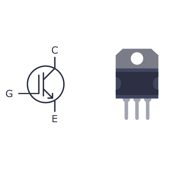
    IGBT stands for Insulated Gate Bipolar Transistor. It is a type of semiconductor device used in electronic switches and amplifiers. The IGBT combines the characteristics of both the insulated gate (like a MOSFET) and the bipolar transistor.

    Here’s a brief overview of its key features:

    1. Structure: The IGBT consists of a metal-oxide-semiconductor field-effect transistor (MOSFET) for the gate control and a bipolar transistor for current-carrying capabilities. The MOSFET provides voltage control, while the bipolar transistor offers high current-carrying capability.
    2. Operation: Like a MOSFET, the IGBT is voltage-driven. When a voltage is applied to the gate terminal, it allows current to flow between the collector and emitter terminals. This makes it suitable for high-power applications.
    3. Applications: IGBTs are commonly used in applications that require high voltage and current capabilities, such as power inverters, motor drives, and power amplifiers. They are preferred in these applications due to their ability to handle high power levels while providing the advantages of voltage-driven control.
    4. Advantages: Some of the advantages of IGBTs include high efficiency, fast switching speeds, and the ability to handle high power levels.

    Overall, IGBTs are crucial components in power electronics, enabling the control of electrical power in various applications, from industrial machinery to renewable energy systems.

  • What is the role of HMIs when monitoring energy?

    What is the role of HMIs when monitoring energy?

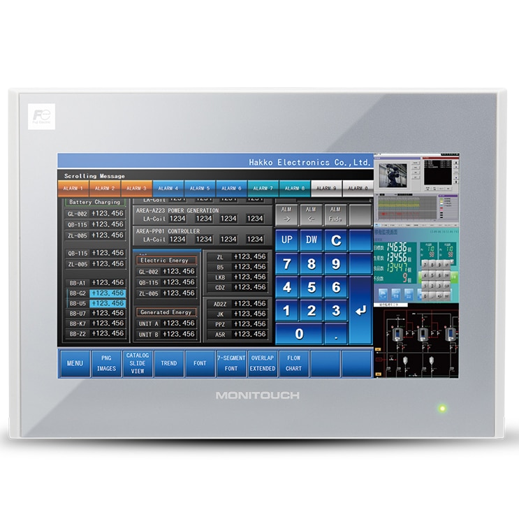
    Thanks to the use of HMI software, systems controlling wind energy and wind turbines are effectively monitored and maintained. For example, electrical utility companies benefit greatly from HMIs. These operations can manage over 3500 MW of wind power spread across multiple states. The layout of the control center contains a system analysis department overseeing the performance parameters of wind turbines nationwide. Moreover, experts continually monitor weather conditions and have the capacity to shut down specific turbines in the event of adverse weather. A key element ensuring the efficiency of the control center is an HMI software, which serves to present, control, oversee, and analyze data collected from various installations. Serving as the central nervous system for numerous wind farms across the country, the HMI unit empowers operators to easily oversee the behavior of the plants and make adjustments to power factors, voltage, and reactive power when necessary.

    Each turbine comes equipped with a control box that houses a PLC, a power converter, and control boards. The PLC transmits the collected data to a remote-control system via an Ethernet-based LAN. The primary communication protocol utilized is OPC, chosen for its ability to facilitate interoperability and achieve the highest possible real-time data exchange rate. Once all the data is funneled to the control center, it is taken up by the HMI software. This software then takes charge of displaying, managing, and analyzing the data, working in tandem with human intervention. The control center also possesses the capability to offer management services to any wind energy facility owner. It oversees the operation of thousands of wind turbines, each of which is equipped with 300–350 I/O data points and is managed by various servers. While the initial investment was substantial, after rigorous testing and the development of an expansion template, operational and economic efficiency experienced a significant boost. Thanks to the HMI software, the control center can effectively monitor and maintain all aspects of wind energy. The involvement of HMIs in other energy resources may even grow as new methods of integrating technology into these burgeoning renewable energy sectors emerge.


  • How does a pressure transmitter work?

    How does a pressure transmitter work?

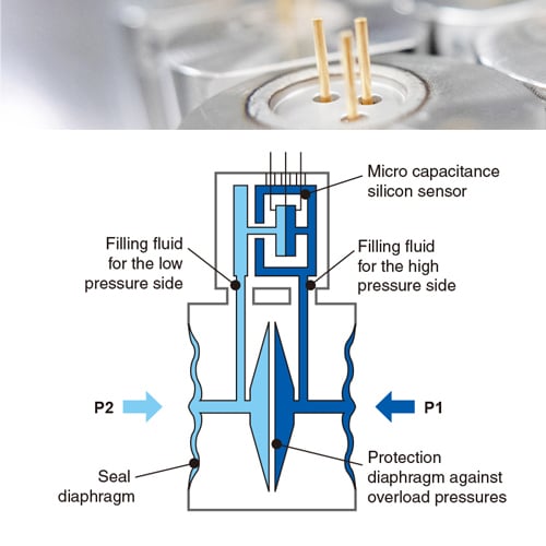
    The pressure of the measured fluid is applied to an internal measuring element through a fitting and then a mechanical interface – measuring membrane. The electronic measuring element converts the pressure into a raw signal. There are different measurement technologies:

    • The piezoresistive pressure sensor measures the force applied to a metal diaphragm.
      The pressure exerted deforms the diaphragm which transmits the pressure variation via an intermediate incompressible fluid (oil or water). This deforms a piezoresistive silicon element (Wheatstone bridge). This element is a variable electrical resistance which converts the strain into an ohmic value.
    • The capacitive pressure sensor measures the force applied to a metal or ceramic membrane. The pressure exerted distorts the membrane, which transmits the pressure variation via an intermediate incompressible fluid (oil or water). This deforms a capacitive silicon element.
      This element is a variable capacitor that converts deformation into a capacitive value.
      The frequency resonant pressure sensor
      The voltage gauge sensor

    The signal from the measuring element is then filtered, amplified, temperature compensated and then formatted into an analog signal. The analog output signal is transmitted via an electrical connector.

    How to calibrate a pressure transmitter:
    Industrial pressure transmitters require periodic calibration to ensure accurate pressure measurement.
    The calibration period is defined by the manufacturer. Zero (Zero) and full-scale sensor (Span) should be calibrated. Calibration involves applying a reference pressure to the sensor’s mechanical interface, checking the output signal and then applying a compensation. The sensor can be calibrated using an external adjustment screw, a local digital indicator, a programming interface or programming software.
    In order to perform the various manipulations, it may be necessary to have an isolated faucet or manifold on the pressure transmitter.

    How to install a pressure transmitter:
    The pressure sensor can be fixed with a mechanical connection to the measuring organ or to the piping where the pressure is to be measured. Special precautions should be taken depending on pressure and temperature conditions. The sensor output signal can be connected to a display system (display, recorder or supervision) or an PLC to drive a control device.

    How to check a pressure transmitter:
    A pressure sensor can be tested by applying a reference pressure to the process connection and by checking the signal of the measured analog output or the value displayed on the indicator.

    How to set up a pressure transmitter:
    There are different ways to set up pressure sensors. Pressure sensors can have a local digital indicator that can be adjusted to adjust the parameters. They can also be configured remotely with a programming interface (hand held communicator) or a configuration software via the digital signal and HART protocol.

  • When to upgrade from indicator lights to an HMI

    When to upgrade from indicator lights to an HMI

    The Fundamentals
    To perform component-level fault diagnostics on industrial equipment, the use of charts and diagrams is often necessary. While standard push buttons and indicator lights are adequate for basic monitoring and control functions, they fall short when more complex tasks are required. In such cases, Human-Machine Interfaces (HMIs) become indispensable and significantly expedite the process of fault analysis and recovery. HMIs also become a cost-effective solution when the system involves more than five motions or requires more than ten outputs, in addition to multiple inputs.

    The Function
    The proper positioning and functionality of your equipment have a significant impact on the level of control needed and, consequently, the choice of monitoring system. When the equipment serves as the central point of a production line, an HMI is the superior choice. In such a scenario, an HMI not only acts as a central interface for the equipment but also facilitates connections to other systems like OPC UA, Modbus, ODBC, and more. The ability to connect HMIs to networks is a primary incentive for system integrators to transition from traditional push-button solutions. Data monitored through HMIs can be stored in a cloud-based database, offering location-independent access to users. Similarly, remote access to control, tied to a computer program, introduces automation capabilities. The features mentioned above are not available in systems equipped with indicator lights and push buttons. However, there are situations where such advanced capabilities are unnecessary for equipment to function. Installing an HMI in a scenario where the equipment undergoes minimal changes during its lifespan or has no significant impact on core processes would only add costs that could be allocated elsewhere.

    The Upgrade
    “If it’s not broken, don’t try to fix it” is a motto that many decision-makers continue to rely on, often without realizing the missed opportunities. The landscape of automation is undergoing dynamic changes, with an increasing number of end-users embracing the practice of engaging with a single screen containing all the necessary information and tools, rather than relying on a cluster of hardware. Transitioning to an HMI-based solution not only enhances the user-friendliness of your machinery but also elicits quicker responses from the newer generation of workers. Furthermore, implementing such a solution empowers businesses to maintain their competitive edge by becoming more accessible to their clients. How? By employing access control methods such as usernames and passwords, companies can control the level of interaction for different tiers of clients and employees, fostering transparency and interactivity in their operations. This approach is particularly advantageous when the HMI is networked, as it enables corporate divisions to make more informed decisions without physically visiting the field.

  • How to choose a pressure transmitter? 

    How to choose a pressure transmitter? 

    The pressure sensor should be chosen based on the fluid to be measured and the conditions of service of the application. It is necessary to define:

    • The fluid to be measured such as air, gas, steam, water or other liquid and its characteristics (density, viscosity…)
    • The fluid process operating conditions:
      • the pressure
      • the temperature
      • the corrosion
    • The measurement type:
      • pressure measurement
      • flow measurement
      • level measurement
      • density measurement
    • The type of pressure to be measured (relative pressure, absolute pressure, differential pressure)
    • The pressure measurement range
    • The measurement dynamic (rangeability) : the difference between the smallest measured value and the highest measured value
    • The measurement accuracy
    • The measurement response time
    • The mechanical interface or the process connection (screwed, flanged)
    • The output signal: analog and/or digital
    • climate environment and associated constraints
      • the ambient temperature
      • the relative ambient humidity
      • the dust content
      • the corrosive gas content
      • the waterproofness and IP tightness level
    • The industrial environment, associated constraints existing regulations
      • the use in explosive atmosphere and areas
        • the dust
        • the explosiveness
      • the electromagnetic waves (CEM)
      • the vibrations
  • What is the difference between a discrete IGBT and an IGBT module?

    What is the difference between a discrete IGBT and an IGBT module?

    The primary difference between a discrete IGBT (Insulated Gate Bipolar Transistor) and an IGBT module lies in their packaging and integration.

    1. Discrete IGBT:
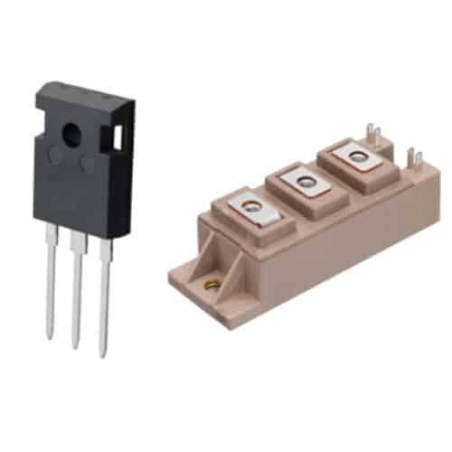
      • Individual Component: A discrete IGBT is a standalone semiconductor device that includes the IGBT chip, usually mounted on a small package. It often has three terminals: collector, emitter, and gate.
      • Single-Chip Design: In a discrete IGBT, the IGBT chip is a single unit, and its control and protection circuitry, if required, are typically external components connected to the device.
    2. IGBT Module:
      • Integrated Design: An IGBT module is a more integrated solution that combines one or more IGBT chips with additional components such as diodes, gate drivers, and sometimes temperature and overcurrent protection circuits.
      • Modular Package: The multiple components are housed in a single package, providing a compact and easy-to-install solution. This modular design simplifies the connection and thermal management of the IGBT system.
      • Multiple IGBTs: Some IGBT modules contain multiple IGBT chips in parallel or in series, allowing for higher voltage or current handling capabilities.

    Key Differences:

    • Integration: The level of integration is the primary distinction. A discrete IGBT is a single, standalone device, while an IGBT module integrates multiple components into a single package.
    • Components: An IGBT module includes not only the IGBT chips but also other components like diodes and gate drivers, streamlining the design and assembly process.
    • Applications: Discrete IGBTs are often used in applications where customization and flexibility are crucial, as designers have more control over the external components. IGBT modules, on the other hand, are convenient in applications where a compact and integrated solution is preferred, such as motor drives, power inverters, and other power electronics systems.
    • Complexity: IGBT modules tend to be more complex due to the integration of multiple components. Discrete IGBTs offer a simpler design but may require additional external components.

    The choice between a discrete IGBT and an IGBT module depends on the specific requirements of the application, including factors such as power rating, space constraints, ease of assembly, and the level of integration desired.

  • What are regenerative blowers?

    What are regenerative blowers?

    Single-Stage and Dual-Stage Regenerative Blowers

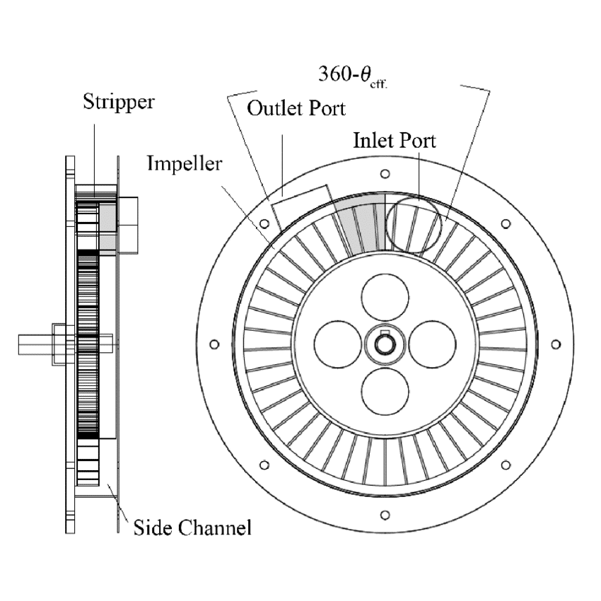
    The working principle of single-stage and dual-stage regenerative blowers is as follows: air is drawn in through the vacuum side or inlet as the impeller rotates inside the blower housing. After the air or gas inside the housing has reached maximum pressure, the impeller accelerates it and releases it through the exhaust outlet, also known as the pressure side.

    The most popular kind of regenerative blower is a single-stage blower, which exhausts air to the application after completing one full rotation of the internal air channel. Because the airflow is redirected around the impeller for a second rotation before being exhausted, dual-stage regenerative blowers are able to produce significantly more pressure or vacuum than their single-stage counterparts. As a result, the air becomes more laminar, which significantly raises the air’s conveyed velocity pressure.


  • How do regenerative blowers work?

    How do regenerative blowers work?

    Regenerative blowers use an electric motor to rotate multiple vane impellers inside their chamber. The rotational force pushes and compresses the air as it enters through the inlet. The procedure keeps going as the blower continuously draws in more air, compressing it and forcing it to the outer edges of its impellers. The air that has been fully compressed is then gathered and sent to the outlet.

    Regenerative blowers function similarly to the two blower types mentioned above, but because of their extremely tight tolerance, they behave like positive displacement blowers in that the majority of the gas is forced through by internal slip (clearances), and they also use the impeller’s velocity to provide pressure, just like centrifugal blowers do. This blower’s typical flow rate, vacuum, and pressure range are up to 1500 CFM, 20″HG vacuum, or 15 PSI at its highest.


  • What characteristics should we look at when searching for an industrial pushbutton switch?

    What characteristics should we look at when searching for an industrial pushbutton switch?

    Each application is unique, and therefore, when selecting an industrial pushbutton switch, several key characteristics need to be considered to ensure it meets the operational and environmental requirements.

    Here are the important factors to look at:

    1. Type of Operation: Determine whether you need a momentary or maintained (latching) pushbutton. Momentary buttons return to their default position when released, while maintained buttons stay in their new position until actuated again.
    2. Contact Configuration: Look at the number and type of contacts, such as normally open (NO), normally closed (NC), or a combination. This should match the control logic of your application.
    3. Current and Voltage Rating: The switch should be able to handle the current and voltage of the circuit it will control. Ensure these ratings match or exceed the requirements of your application.
    4. Environmental Ratings: Consider the environmental conditions where the switch will be used. This includes factors like temperature range, humidity, dust, and water exposure. Industrial switches often come with IP (Ingress Protection) ratings that indicate their resistance to solids and liquids.
    5. Size and Mounting: The physical size of the pushbutton and its mounting style should fit your panel or control box. Common mounting styles include panel mount, PCB mount, and surface mount.
    6. Material and Build Quality: Industrial environments can be harsh, so the switch should be robust and made from high-quality materials. Metals like stainless steel or durable plastics are common in industrial switches.
    7. Actuation Force: This is the amount of force required to activate the switch. It should be suitable for the operator’s convenience and prevent accidental activation.
    8. Color and Labeling: For safety and ease of use, pushbuttons are often color-coded and labeled according to their function (e.g., red for stop, green for start). Make sure the switch aligns with standard practices and is clearly identifiable.
    9. Illumination: Consider if you need the pushbutton to be illuminated for visibility. Illuminated pushbuttons are especially useful in low-light conditions or to indicate the status of the switch or associated equipment.
    10. Safety Features: In some applications, you may require additional safety features like shrouds to prevent accidental activation, or key-operated switches for restricted access.
    11. Compatibility with Control Systems: Ensure the switch is compatible with the control logic and voltage levels of your existing control systems.
    12. Certifications and Standards: Check for compliance with relevant industrial standards and certifications, especially those related to safety and quality.
    13. Ease of Installation and Maintenance: The switch should be easy to install and maintain, with readily available replacement parts if necessary.
    14. Manufacturer Reputation: Choose a reputable manufacturer known for producing reliable and durable industrial components.

    It’s critical to balance all of these factors to select an industrial pushbutton switch that is optimal for the operational demands and environmental conditions of your specific application.

  • What are the benefits of using an AC drive?

    What are the benefits of using an AC drive?

    An AC drive, also known as a variable frequency drive (VFD) or adjustable speed drive (ASD), is a device that controls the speed, torque, and direction of an AC motor by varying the frequency and voltage of the electrical power supplied to it. AC drives offer several benefits in various industrial and commercial applications:

    1. Energy Efficiency: AC drives can help reduce energy consumption by controlling the speed of motors. By adjusting the motor’s speed to match the load requirements, you can save energy and reduce electricity costs, especially in applications with varying loads.
    2. Improved Process Control: AC drives provide precise control over motor speed and torque, enabling better regulation of industrial processes. This helps maintain consistent product quality and operational efficiency.
    3. Soft Start and Stop: AC drives offer soft-start and soft-stop capabilities, which reduce mechanical stress on equipment and extend the lifespan of motors and connected machinery. This feature is particularly useful in applications where abrupt starts and stops can cause damage.
    4. Reduced Mechanical Wear: By starting and stopping motors gradually and smoothly, AC drives reduce wear and tear on equipment, minimizing maintenance and downtime.
    5. Speed and Torque Control: AC drives allow for precise control of motor speed and torque, making them suitable for applications that require different speeds at different times, such as conveyor systems and fans.
    6. Adaptability to Changing Loads: AC drives can adjust motor speed in real time to match variations in load, ensuring optimal performance and energy efficiency.
    7. Energy Cost Savings: By reducing energy consumption and improving efficiency, AC drives can lead to significant cost savings over time, making them a cost-effective investment.
    8. Power Factor Improvement: AC drives can improve the power factor of a system, leading to a reduction in reactive power and potential cost savings on utility bills.
    9. Reduced Maintenance: With soft-start and stop features, AC drives help reduce mechanical stress, which in turn lowers maintenance requirements and extends the lifespan of equipment.
    10. Noise Reduction: Slower motor speeds, made possible by AC drives, can reduce noise levels in industrial environments, creating a more comfortable and safe workplace.
    11. Process Optimization: AC drives can be integrated with automation systems and control algorithms, allowing for more sophisticated process optimization, which is essential in many manufacturing and industrial operations.
    12. Environmental Benefits: Lower energy consumption and reduced wear and tear on equipment can lead to a smaller carbon footprint and contribute to sustainability efforts.

    It’s important to note that the benefits of using an AC drive can vary depending on the specific application and the efficiency of the system it’s integrated into. When considering the implementation of an AC drive, it’s essential to perform a detailed analysis to determine potential energy savings and operational improvements for your particular use case.