Call today (732) 560-9410 

Author: Brian Ribeiro

  • What is an IGBT?

    What is an IGBT?


    IGBT stands for Insulated Gate Bipolar Transistor. It is a type of semiconductor device used in electronic switches and amplifiers. The IGBT combines the characteristics of both the insulated gate (like a MOSFET) and the bipolar transistor.

    Here’s a brief overview of its key features:

    1. Structure: The IGBT consists of a metal-oxide-semiconductor field-effect transistor (MOSFET) for the gate control and a bipolar transistor for current-carrying capabilities. The MOSFET provides voltage control, while the bipolar transistor offers high current-carrying capability.
    2. Operation: Like a MOSFET, the IGBT is voltage-driven. When a voltage is applied to the gate terminal, it allows current to flow between the collector and emitter terminals. This makes it suitable for high-power applications.
    3. Applications: IGBTs are commonly used in applications that require high voltage and current capabilities, such as power inverters, motor drives, and power amplifiers. They are preferred in these applications due to their ability to handle high power levels while providing the advantages of voltage-driven control.
    4. Advantages: Some of the advantages of IGBTs include high efficiency, fast switching speeds, and the ability to handle high power levels.

    Overall, IGBTs are crucial components in power electronics, enabling the control of electrical power in various applications, from industrial machinery to renewable energy systems.

  • What is the role of HMIs when monitoring energy?

    What is the role of HMIs when monitoring energy?

    Thanks to the use of HMI software, systems controlling wind energy and wind turbines are effectively monitored and maintained. For example, electrical utility companies benefit greatly from HMIs. These operations can manage over 3500 MW of wind power spread across multiple states. The layout of the control center contains a system analysis department overseeing the performance parameters of wind turbines nationwide. Moreover, experts continually monitor weather conditions and have the capacity to shut down specific turbines in the event of adverse weather. A key element ensuring the efficiency of the control center is an HMI software, which serves to present, control, oversee, and analyze data collected from various installations. Serving as the central nervous system for numerous wind farms across the country, the HMI unit empowers operators to easily oversee the behavior of the plants and make adjustments to power factors, voltage, and reactive power when necessary.

    Each turbine comes equipped with a control box that houses a PLC, a power converter, and control boards. The PLC transmits the collected data to a remote-control system via an Ethernet-based LAN. The primary communication protocol utilized is OPC, chosen for its ability to facilitate interoperability and achieve the highest possible real-time data exchange rate. Once all the data is funneled to the control center, it is taken up by the HMI software. This software then takes charge of displaying, managing, and analyzing the data, working in tandem with human intervention. The control center also possesses the capability to offer management services to any wind energy facility owner. It oversees the operation of thousands of wind turbines, each of which is equipped with 300–350 I/O data points and is managed by various servers. While the initial investment was substantial, after rigorous testing and the development of an expansion template, operational and economic efficiency experienced a significant boost. Thanks to the HMI software, the control center can effectively monitor and maintain all aspects of wind energy. The involvement of HMIs in other energy resources may even grow as new methods of integrating technology into these burgeoning renewable energy sectors emerge.


  • How does a pressure transmitter work?

    How does a pressure transmitter work?

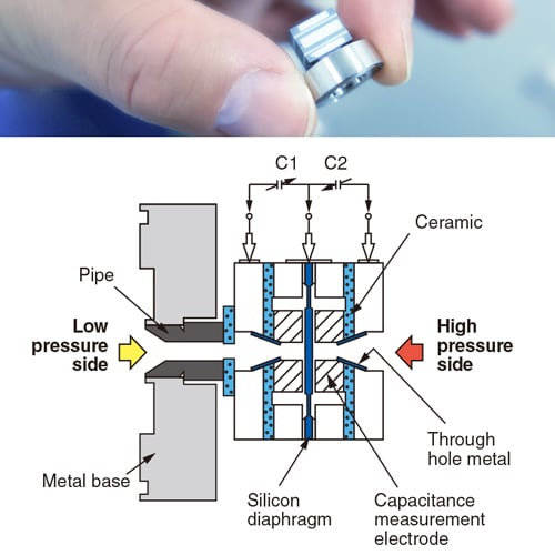
    The pressure of the measured fluid is applied to an internal measuring element through a fitting and then a mechanical interface – measuring membrane. The electronic measuring element converts the pressure into a raw signal. There are different measurement technologies:

    • The piezoresistive pressure sensor measures the force applied to a metal diaphragm.
      The pressure exerted deforms the diaphragm which transmits the pressure variation via an intermediate incompressible fluid (oil or water). This deforms a piezoresistive silicon element (Wheatstone bridge). This element is a variable electrical resistance which converts the strain into an ohmic value.
    • The capacitive pressure sensor measures the force applied to a metal or ceramic membrane. The pressure exerted distorts the membrane, which transmits the pressure variation via an intermediate incompressible fluid (oil or water). This deforms a capacitive silicon element.
      This element is a variable capacitor that converts deformation into a capacitive value.
      The frequency resonant pressure sensor
      The voltage gauge sensor

    The signal from the measuring element is then filtered, amplified, temperature compensated and then formatted into an analog signal. The analog output signal is transmitted via an electrical connector.

    How to calibrate a pressure transmitter:
    Industrial pressure transmitters require periodic calibration to ensure accurate pressure measurement.
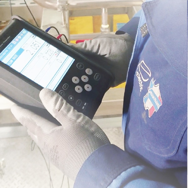
    The calibration period is defined by the manufacturer. Zero (Zero) and full-scale sensor (Span) should be calibrated. Calibration involves applying a reference pressure to the sensor’s mechanical interface, checking the output signal and then applying a compensation. The sensor can be calibrated using an external adjustment screw, a local digital indicator, a programming interface or programming software.
    In order to perform the various manipulations, it may be necessary to have an isolated faucet or manifold on the pressure transmitter.

    How to install a pressure transmitter:
    The pressure sensor can be fixed with a mechanical connection to the measuring organ or to the piping where the pressure is to be measured. Special precautions should be taken depending on pressure and temperature conditions. The sensor output signal can be connected to a display system (display, recorder or supervision) or an PLC to drive a control device.

    How to check a pressure transmitter:
    A pressure sensor can be tested by applying a reference pressure to the process connection and by checking the signal of the measured analog output or the value displayed on the indicator.

    How to set up a pressure transmitter:
    There are different ways to set up pressure sensors. Pressure sensors can have a local digital indicator that can be adjusted to adjust the parameters. They can also be configured remotely with a programming interface (hand held communicator) or a configuration software via the digital signal and HART protocol.

  • When to upgrade from indicator lights to an HMI

    When to upgrade from indicator lights to an HMI

    The Fundamentals
    To perform component-level fault diagnostics on industrial equipment, the use of charts and diagrams is often necessary. While standard push buttons and indicator lights are adequate for basic monitoring and control functions, they fall short when more complex tasks are required. In such cases, Human-Machine Interfaces (HMIs) become indispensable and significantly expedite the process of fault analysis and recovery. HMIs also become a cost-effective solution when the system involves more than five motions or requires more than ten outputs, in addition to multiple inputs.

    The Function
    The proper positioning and functionality of your equipment have a significant impact on the level of control needed and, consequently, the choice of monitoring system. When the equipment serves as the central point of a production line, an HMI is the superior choice. In such a scenario, an HMI not only acts as a central interface for the equipment but also facilitates connections to other systems like OPC UA, Modbus, ODBC, and more. The ability to connect HMIs to networks is a primary incentive for system integrators to transition from traditional push-button solutions. Data monitored through HMIs can be stored in a cloud-based database, offering location-independent access to users. Similarly, remote access to control, tied to a computer program, introduces automation capabilities. The features mentioned above are not available in systems equipped with indicator lights and push buttons. However, there are situations where such advanced capabilities are unnecessary for equipment to function. Installing an HMI in a scenario where the equipment undergoes minimal changes during its lifespan or has no significant impact on core processes would only add costs that could be allocated elsewhere.

    The Upgrade
    “If it’s not broken, don’t try to fix it” is a motto that many decision-makers continue to rely on, often without realizing the missed opportunities. The landscape of automation is undergoing dynamic changes, with an increasing number of end-users embracing the practice of engaging with a single screen containing all the necessary information and tools, rather than relying on a cluster of hardware. Transitioning to an HMI-based solution not only enhances the user-friendliness of your machinery but also elicits quicker responses from the newer generation of workers. Furthermore, implementing such a solution empowers businesses to maintain their competitive edge by becoming more accessible to their clients. How? By employing access control methods such as usernames and passwords, companies can control the level of interaction for different tiers of clients and employees, fostering transparency and interactivity in their operations. This approach is particularly advantageous when the HMI is networked, as it enables corporate divisions to make more informed decisions without physically visiting the field.