Greater production capacity in comparison to high pressure air: if sized properly, regenerative blowers can produce the volume pressure balance needed for the best possible product flow.
Regenerative blowers are generally quieter than continuous-duty blowers (PD blowers). It should be noted, though, that PD blowers can be mounted up to 100 feet away from the bagger outside of the building, up on a roof, or in any other place that won’t annoy operators. Regenerative blowers, on the other hand, usually have to be mounted at the bagger’s location.
The ability to mount on board the bagger means that all electrical and pneumatic connections can be pre-wired and plumbinged at the factory, saving money on installation costs. As a result, the plant site’s installation expenses were decreased.
Cons:
Regenerative blowers must be installed on or very near to baggers in order to minimize noise pollution to operators and reduce blower dust and dirt. This will reduce the likelihood of unplanned, costly maintenance.
When comparing apples-to-apples air volume output, regenerative blowers usually need more horsepower to produce the same airflow as a smaller PD blower. This results in higher energy consumption and no significant cost savings at purchase (compared to a PD blower).
The upstart of a bag filled by a regenerative blower will take a little longer than that of a bag filled on the same machine using a PD blower because regenerative blowers do not build pressure as quickly as PD blowers.
Designing an AC Drive (also known as a variable frequency drive or VFD) involves considering several important criteria to ensure the drive meets the specific application’s requirements and operates efficiently and reliably. Here are some key design criteria to account for:
Load Requirements: Understand the load characteristics, such as the motor type (induction, synchronous, etc.), load torque, speed range, and duty cycle. This information is crucial for selecting the appropriate drive.
Motor Compatibility: Ensure that the AC drive is compatible with the motor, both in terms of voltage, current, and frequency ratings. The drive must match the motor’s specifications.
Voltage and Power Ratings: Determine the voltage and power rating of the AC drive, ensuring it can handle the power requirements of the motor and the connected system.
Frequency Range: Select a drive with a frequency range that accommodates the desired speed control, including the minimum and maximum speeds required for the application.
Control Methods: Decide on the control method for the AC drive, such as V/Hz (Volts per Hertz), vector control, or sensorless vector control, based on the application’s precision and performance needs.
Overload Capacity: Consider the drive’s overload capacity to handle temporary increases in load or starting currents without tripping or overheating.
Environmental Conditions: Account for the environmental conditions where the drive will be installed, including temperature, humidity, dust, and corrosive factors, and select a drive with suitable protection and cooling measures.
Enclosure Type: Choose an appropriate enclosure type, such as IP rating, NEMA rating, or specific hazardous area certifications if the drive will be exposed to special environmental conditions.
Communication Interfaces: Determine if the drive needs to communicate with other control systems or PLCs and select a drive with compatible communication interfaces (e.g., Modbus, Profibus, Ethernet).
Motor Feedback: Decide whether the application requires motor feedback devices (e.g., encoders, resolvers) for position or speed control and ensure the drive supports these options.
Harmonic Mitigation: Consider harmonic distortion in the power supply and select a drive with built-in or external harmonic filters, if needed, to comply with power quality standards.
Redundancy and Fault Tolerance: Evaluate the need for redundancy or fault-tolerant configurations to ensure system reliability in critical applications.
Protective Features: Look for protective features like overcurrent, overvoltage, undervoltage, overtemperature, and short-circuit protection to prevent damage to the drive and motor.
Maintenance and Serviceability: Choose a drive that is easy to install, commission, and maintain to minimize downtime.
Compliance and Standards: Ensure that the AC drive complies with relevant safety and industry standards, such as CE, UL, and ISO, depending on the application and location.
Energy Efficiency: Consider the drive’s energy efficiency and its impact on the overall system’s operating costs.
Future Expandability: Think about future system upgrades and expansion, and select a drive that can adapt to changing requirements.
Each application may have unique requirements, so it’s essential to work closely with drive manufacturers and engineering experts to select and design the most suitable AC drive for your specific project.
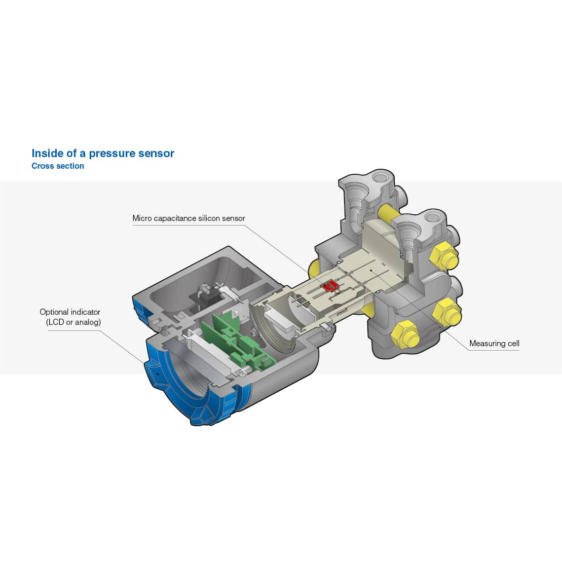
Rangeability and turndown ratio are fundamental attributes of pressure transmitters. Simply put, rangeability refers to the ratio of maximum to minimum pressure that a pressure transmitter can accurately measure. Turndown ratio, often synonymous with rangeability, specifically denotes the maximum capacity a device has over its minimum measurable capability.
Rangeability, commonly referred to as turndown ratio, is a critical parameter in control systems, especially when dealing with process pressure transmitters. Whether it’s the turndown ratio of a differential pressure transmitter, a gauge pressure transmitter or an absolute pressure transmitter, it’s a simple formula that compares the maximum measurable range of a device to its minimum measurable range.
This ratio is often expressed as a number such as 3:1, 5:1, or even 100:1, indicating that the sensor is capable of accurately measuring pressures within that span. For example, in a transmitter with a 5:1 turndown ratio, if the maximum pressure (the high end) it can measure is 100 units, then it can accurately measure down to 20 units, which is its low end.
Let’s dig a little deeper with a few definitions:
The Range is the measurement limit and covers from the minimum pressure to the maximum pressure that the pressure transmitter cell can measure, for example from 0 to 100 bar. The maximum measurement span is 100 bar.
Upper Range Limit (URL) refers to the highest pressure that the transmitter was designed to measure, respected the cell upper range limit.
The Lower Range Limit (LRL)refers to the lowest pressure that the transmitter was designed to measure, respected the cell lower range limit.
URV (Upper Range Value) is the maximum pressure at which the pressure transmitter is calibrated. It corresponds to the lowest point of the output scale, such as the 4mA point in a 4 to 20mA output signal.
LRV (Lower Range Value) is the minimum pressure at which the pressure transmitter is calibrated. Its corresponds to the lowest point of the output scale, such as the 4mA point in a 4 to 20mA output signal.
Span (Calibrated span) is the working range that is equal to URV – LRV. This is the equivalent of the 4 to 20mA output signal.
Turndown (TD) or Rangeabilityof a pressure transmitter is calculated by dividing the maximum pressure the device can measure (Upper Range Limit, or URL) by the minimum pressure it can measure accurately (minimum calibrated span).
The understanding of rangeability and turndown ratio is crucial in various applications where pressure needs to be monitored and controlled. It’s especially important in fluid and gas control systems where accurately measuring and maintaining pressure levels is crucial to the operation’s success.
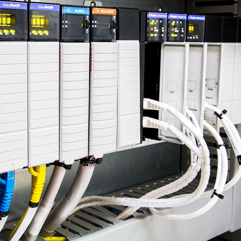
The Progression In its early days, the PLC was relatively unsophisticated, with only a fraction of the features it boasts today. Notably, it was exceptionally expensive at the time. Over the decades, the PLC expanded considerably but adhered to the fundamental definition of being an electronic device with programmable memory, I/Os, and a power supply, executing user-entered instructions. It resembled a computer but required a programming device to correctly code addresses.
The Transition Initially employed for discrete and process-control applications, as sophistication increased, the PLC transitioned into a comprehensive automation controller. The price/performance ratios underwent a drastic change, with today’s PLCs being 30 times more efficient than their counterparts from a decade ago. Technological advancements made electronics more affordable on a broader scale.
A New Era Simultaneously, software also underwent significant evolution. The introduction of Windows 95 ushered in a new era of computer-based programming, significantly reducing development time. Over time, a clear pattern emerges: PLCs are evolving into appliances, requiring internet connectivity for optimal performance. This evolution has given rise to another device—the Programmable Logical Controller or PAC.
The Evolution By definition, a PAC is a PLC, encompassing all the elements of a traditional PLC. PACs have the capacity to manage discrete, drive, motion, and safety control applications from a common platform, tasks that PLCs handled a decade or two ago. The development of PACs is deeply influenced by evolution, integrating components and functionalities into a dedicated box to simplify on-site challenges for engineers, such as adding axes of motion. PACs have emerged as a parallel automation technology, in some ways overshadowing PLCs due to their enhanced ease-of-use and simplification of complex processes found in the latter.
When selecting a contactor for an electrical or industrial application, there are several key characteristics and factors to consider to ensure it meets the specific requirements of your system.
Here are the main aspects to look at:
Rated Operational Voltage: Check the maximum voltage level the contactor can handle. This should match or exceed the voltage level of the circuit it will be used in.
Current Rating: This is one of the most critical factors. The contactor should be able to handle the maximum current that the circuit will draw. This includes both the normal operating current and the inrush current (initial surge current) typical in motors and transformers.
AC or DC Operation: Contactor coils can be designed for AC or DC operation. The choice depends on the control voltage available in your system.
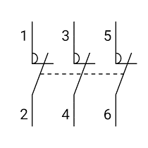
Contact Configuration: Look at the number of contacts and their type – normally open (NO) or normally closed (NC). This should align with the control logic of your system.
Size and Mounting Requirements: Consider the physical size of the contactor and how it will be mounted in your panel or system.
Coil Voltage: The control voltage required to operate the contactor’s coil. This should be compatible with the control system used to operate the contactor.
Environmental Conditions: Consider the operating environment. Factors such as temperature, humidity, and the presence of dust or corrosive materials can affect the contactor’s performance and lifespan.
Duty Cycle: Ensure the contactor is rated for the type of load and operation frequency it will encounter. Different types are available for continuous, intermittent, or high-frequency operation.
Auxiliary Contacts: Some contactors come with auxiliary contacts used for signaling and interlocking purposes. Check if your application requires these.
Manufacturer and Brand Reputation: Choose a reliable brand known for quality and durability, especially for applications in critical systems.
Certifications and Standards Compliance: Ensure the contactor meets relevant industry standards and certifications, which might be required for legal or safety compliance in your region or industry.
Overload Protection Integration: Some contactors can be integrated with thermal or electronic overload relays for motor protection. Consider this if you’re using the contactor for motor control.
Arc Suppression Features: In higher-power applications, the contactor’s ability to suppress and extinguish electric arcs generated during switching is important.
Ease of Installation and Maintenance: Look for contactors that are easy to install and maintain, especially if frequent servicing is anticipated.
By carefully evaluating these factors, you can select a contactor that efficiently meets the specific needs of your application and ensures reliable performance.
Power MOSFETs (Metal-Oxide-Semiconductor Field-Effect Transistors) are semiconductor devices widely used in power electronics for various applications, including power supplies, motor drives, voltage regulators, and amplifiers.
Here are some key characteristics of power MOSFETs:
Voltage-Controlled Device:
Power MOSFETs are voltage-controlled devices. The gate terminal voltage determines the conductivity between the source and drain terminals.
Three Terminals:
Like other MOSFETs, power MOSFETs typically have three terminals: gate (G), source (S), and drain (D).
Operating Principle:
When a voltage is applied to the gate terminal, an electric field is generated, creating a channel for current flow between the source and drain terminals. The conductivity of this channel is controlled by the applied gate voltage.
On-State Resistance (Rdson):
Power MOSFETs exhibit low on-state resistance (Rdson) when conducting, which leads to reduced conduction losses and increased efficiency in power electronic systems.
Blocking Voltage (Vds):
Power MOSFETs are designed to handle a specific blocking voltage (Vds) across the drain and source terminals. The maximum voltage rating is a crucial parameter for selecting the right MOSFET for a particular application.
Gate Threshold Voltage (Vth):
The gate threshold voltage is the minimum voltage required to turn the MOSFET on. It is an important parameter in determining the MOSFET’s operating conditions.
Gate Drive Voltage (Vgs):
The gate drive voltage is the voltage applied between the gate and source terminals to turn the MOSFET on. Proper gate drive is essential for achieving optimal switching performance.
Gate Charge (Qg):
Gate charge refers to the total electric charge required to turn the MOSFET on or off. It is a critical parameter for evaluating the switching characteristics of the MOSFET and influences the gate drive requirements.
Switching Speed:
Power MOSFETs have relatively fast switching speeds compared to other power devices like IGBTs (Insulated Gate Bipolar Transistors). This characteristic makes them suitable for high-frequency applications.
Body Diode:
Power MOSFETs inherently have a parasitic body diode between the source and drain terminals. This diode conducts when the MOSFET is reverse-biased, providing a path for the reverse current.
Temperature Dependence:
The performance of power MOSFETs is influenced by temperature. The temperature coefficient of various parameters, such as threshold voltage and on-state resistance, is an important consideration in the design of power electronic systems.
Package Types:
Power MOSFETs come in various package types, such as TO-220, TO-247, and surface-mount packages. The choice of package depends on factors like thermal performance and space constraints.
Understanding these characteristics is crucial for selecting the right power MOSFET for a specific application and designing efficient and reliable power electronic systems. Designers need to consider parameters like on-state resistance, voltage ratings, switching speed, and thermal performance to optimize the performance of their circuits.
An RB-IGBT stands for Reverse Blocking Insulated Gate Bipolar Transistor. It is a type of power semiconductor device that combines the simple gate-drive characteristics of MOSFETs (Metal-Oxide-Semiconductor Field-Effect Transistors) with the high-current and low-saturation-voltage capability of bipolar transistors. The “reverse blocking” capability means that the RB-IGBT can block current flow in both the forward and reverse directions when it is turned off, unlike standard IGBTs which can only block current in the forward direction.
How RB-IGBTs are Used in UPS Systems
RB-IGBTs are particularly useful in Uninterruptible Power Supply (UPS) systems for several reasons:
Efficiency and Performance: The efficiency of a UPS is crucial, especially for systems designed to support critical loads over extended periods. RB-IGBTs offer high efficiency and fast switching speeds, which are essential for minimizing energy losses and improving UPS performance. This results in a UPS that can provide clean and stable power with lower operational costs.
Bidirectional Power Flow: The reverse blocking capability of RB-IGBTs allows for more efficient management of bidirectional power flow. This is particularly beneficial in UPS systems that feature energy storage or are integrated with renewable energy sources. For instance, in applications where a UPS is connected to a battery storage system or solar panels, RB-IGBTs can efficiently manage the charging and discharging processes, ensuring optimal power flow from and to the grid.
Size and Weight Reduction: The use of RB-IGBTs can contribute to reducing the size and weight of UPS systems. Their high efficiency and fast switching capabilities allow for the use of smaller cooling systems and transformers, which in turn can lead to a more compact and lightweight UPS design. This is especially advantageous for applications where space is at a premium.
Enhanced Protection: In UPS systems, protecting sensitive loads from power quality issues such as voltage sags, surges, and interruptions is paramount. RB-IGBTs enhance the UPS’s ability to quickly respond to and mitigate these issues, providing superior protection for connected equipment.
Scalability and Flexibility: The incorporation of RB-IGBT technology in UPS systems allows for greater scalability and flexibility. This means that the UPS can be easily scaled up to meet growing power demands without compromising on efficiency or performance.
In summary, RB-IGBTs play a critical role in modern UPS systems by enhancing efficiency, performance, and reliability. Their unique properties make them ideal for applications requiring high-quality power delivery and protection, contributing to the development of more advanced, efficient, and compact UPS solutions.
Manual motor starters are devices used to control the operation of electric motors in industrial settings. They serve several key functions:
Starting and Stopping: As the name suggests, manual motor starters allow for the manual starting and stopping of motors. This is typically done through a switch or a button that an operator can engage or disengage.
Overload Protection: They often incorporate overload protection, which helps to safeguard the motor against potential damage caused by overcurrents. This is usually achieved through thermal or magnetic means. The thermal protection works by detecting excessive current over a period, indicative of an overload condition, while magnetic protection responds to short-circuit conditions.
Short-Circuit Protection: Some manual motor starters may also offer short-circuit protection, although this is often handled by separate devices like fuses or circuit breakers in many installations.
Disconnecting Means: They provide a means of disconnecting the motor from the power source for maintenance or emergency purposes. This feature is crucial for ensuring safety during repairs or when resolving issues with the motor or associated equipment.
Local Control: Manual motor starters allow for local control of a motor, meaning that the start and stop functions can be performed at the motor’s location. This is particularly useful in smaller or simpler systems where centralized control is not necessary or practical.
Adjustable Settings: Many industrial manual motor starters have adjustable settings that allow operators to set overload protection thresholds according to the specific requirements of the motor and the application.
Robust Design: Designed for industrial environments, these starters are typically built to withstand harsh conditions, including dust, moisture, and mechanical vibrations.
Simplicity and Cost-Effectiveness: Manual motor starters are generally simpler and more cost-effective compared to automatic starters or those with more advanced control features. They are well-suited for applications where automatic control is not necessary, or where manual operation provides sufficient control.
In summary, manual motor starters are fundamental components in motor control, offering basic functionalities such as start/stop control, overload protection, and a means of disconnection for maintenance and safety purposes. They are widely used in various industrial applications due to their simplicity, reliability, and cost-effectiveness.
Human Machine Interfaces (HMIs) play a critical role in efficiently monitoring and controlling control systems, whether they are on a small scale or span multiple geographic locations. Regardless of the system’s scope, effective communication is essential as it ensures transparency, rapid responsiveness, and allows decision-makers to free themselves from a specific physical location. These goals can be achieved through three main approaches:
Direct Access: Modern PCs are equipped with hardware that, when combined with well-designed HMI software, facilitates communication. The simplest and most established method is through an HMI’s web server. The procedure involves connecting the HMI to the internet via an Ethernet connection. The company’s data and functions become accessible through web pages and technologies like the cloud, allowing other mobile devices to access them via simple addresses. While security is a growing concern in open communication, web server technologies such as Apache HTTP and Microsoft IIS adhere to the latest security standards, including SSL and HTTPS security, ensuring user data integrity. User rights can be established to enhance security and reduce misuse of authority. Over-reliance on the internet can, however, lead to operational interruptions in the event of network breakdowns.
Onsite IT: A more expensive but reliable approach involves using onsite IT hardware and software. This option provides more power and flexibility for distributing data across multiple devices but requires specialized hardware and software, along with ongoing maintenance. Multiple HMIs within a plant are connected through Ethernet ports, forming an intranet with all the functionalities of the internet, but on a local level. Information can be accessed in the same way as before through various devices, but with greater security and control. Setting up an internal IT network that extends to all corners of the plant and associated offices is necessary. The intranet should ideally be location-independent and connect all company assets, both enterprise and manufacturing. Security is less of a concern, but the network requires high maintenance and constant service to operate without interruptions.
The Cloud: Cloud technologies can revolutionize the way information flows, allowing devices to interact in a more stable, reliable, and resourceful manner. Multiple redundant connections enable each device to connect to the cloud and access HMI functions through smartphone apps. These apps reflect changes across databases and spreadsheets stored in the cloud, which are subsequently reflected in the industrial hardware in place. Cloud systems offer flexibility, affordability, and high security. Examples include Amazon Web Services and Microsoft Cloud, which employ a high level of virtual and physical security and a range of backup mechanisms to ensure uninterrupted operations even in adverse scenarios. The cloud-based system represents the latest and most viable solution for HMI communications with remote devices. The widespread availability of the internet, including 4G cellular networks, and powerful mobile devices have transformed it into an industrial technology poised to establish itself over the coming decades.
A Variable Frequency Drive (VFD), also known as a Variable Speed Drive (VSD) or Adjustable Frequency Drive (AFD), is an electrical device used to control the speed and torque of an electric motor. It does this by varying the frequency and voltage supplied to the motor, which in turn adjusts the motor’s rotational speed. VFDs are commonly used in industrial and commercial applications where precise control of motor speed is required. Here’s how they work and some of their key features:
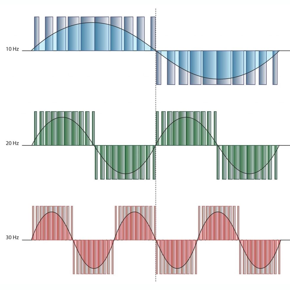
Frequency and Voltage Control: VFDs control the frequency and voltage supplied to an AC (Alternating Current) motor. By varying these parameters, they can increase or decrease the motor’s speed and torque. This allows for precise control of the motor’s performance.
Energy Efficiency: One of the primary benefits of using VFDs is energy savings. They can significantly reduce energy consumption by matching the motor’s speed to the actual requirements of the load. When a motor operates at full speed all the time, it often uses more energy than necessary. VFDs enable motors to run at lower speeds when the load is light, saving electricity.
Soft Start and Stop: VFDs can provide a soft start and stop for motors. This gradual acceleration and deceleration help reduce mechanical stress on equipment and improve the lifespan of the motor and connected machinery.
Precise Control: VFDs offer precise control over motor speed. This is crucial in applications where speed and torque must be adjusted for specific processes, such as conveyor systems, pumps, fans, and compressors.
Dynamic Braking: Some VFDs can perform dynamic braking, which converts excess kinetic energy into electrical energy, dissipated as heat. This feature can help stop a motor quickly and safely.
Motor Protection: VFDs often include built-in protection features, such as overload protection, overvoltage protection, and under-voltage protection, which help prevent damage to the motor and connected equipment.
Reduced Wear and Tear: By avoiding sudden starts and stops, VFDs reduce the mechanical wear and tear on motors and associated machinery. This extends the lifespan of these components and reduces maintenance costs.
Remote Control and Monitoring: Many VFDs can be controlled remotely and integrated into automation systems, allowing for centralized monitoring and control of multiple motors and processes. VFDs are widely used in various industries, including manufacturing, HVAC (Heating, Ventilation, and Air Conditioning), water and wastewater treatment, and transportation, among others. They offer a cost-effective way to improve energy efficiency, process control, and equipment reliability.












 A
A