Author: Brian Ribeiro

  • Why is fluid flow management becoming increasingly important in the manufacturing industry?

    Why is fluid flow management becoming increasingly important in the manufacturing industry?

    The need for accurate measurement and control of fluids is ubiquitous in manufacturing processes, in research laboratories, during the transformation of raw materials into finished products and during packaging. Continuous measurement, control, and analysis of fluid flow using appropriate measurement technologies improve the reliability, performance, and uptime of industrial processes, as well as environmental sustainability and compliance with standards and regulations.

    Industrial fluid flow measurement and control technologies are well established for applications involving large pipes, but accelerating market trends present a distinct and pressing challenge: measuring flow in small pipes. The move towards faster, smaller, more compact and less expensive machines has increased the need to measure fluid flow in small diameter, densely spaced pipes. Examples include semiconductors, pharmaceuticals, biopharmaceuticals and life sciences, food processing, heating, ventilation and air conditioning, and any high-purity water application. Applications in small pipes and confined spaces require a new method of measuring and metering, and not just in terms of size. Manufacturers are looking for accurate, efficient and cost-effective technology that offers ease of use, low or no installation costs, reliable data and low energy consumption.

  • What are manual motor starters?

    What are manual motor starters?

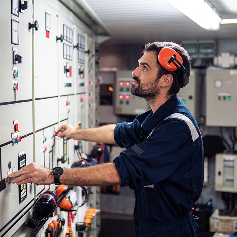
    Manual motor starters are devices used to control the operation of electric motors in industrial settings. They serve several key functions:

    1. Starting and Stopping: As the name suggests, manual motor starters allow for the manual starting and stopping of motors. This is typically done through a switch or a button that an operator can engage or disengage.
    2. Overload Protection: They often incorporate overload protection, which helps to safeguard the motor against potential damage caused by overcurrents. This is usually achieved through thermal or magnetic means. The thermal protection works by detecting excessive current over a period, indicative of an overload condition, while magnetic protection responds to short-circuit conditions.
    3. Short-Circuit Protection: Some manual motor starters may also offer short-circuit protection, although this is often handled by separate devices like fuses or circuit breakers in many installations.
    4. Disconnecting Means: They provide a means of disconnecting the motor from the power source for maintenance or emergency purposes. This feature is crucial for ensuring safety during repairs or when resolving issues with the motor or associated equipment.
    5. Local Control: Manual motor starters allow for local control of a motor, meaning that the start and stop functions can be performed at the motor’s location. This is particularly useful in smaller or simpler systems where centralized control is not necessary or practical.
    6. Adjustable Settings: Many industrial manual motor starters have adjustable settings that allow operators to set overload protection thresholds according to the specific requirements of the motor and the application.
    7. Robust Design: Designed for industrial environments, these starters are typically built to withstand harsh conditions, including dust, moisture, and mechanical vibrations.
    8. Simplicity and Cost-Effectiveness: Manual motor starters are generally simpler and more cost-effective compared to automatic starters or those with more advanced control features. They are well-suited for applications where automatic control is not necessary, or where manual operation provides sufficient control.

    In summary, manual motor starters are fundamental components in motor control, offering basic functionalities such as start/stop control, overload protection, and a means of disconnection for maintenance and safety purposes. They are widely used in various industrial applications due to their simplicity, reliability, and cost-effectiveness.

  • What is the difference between single-phase and three-phase drives?

    What is the difference between single-phase and three-phase drives?

    A Variable Frequency Drive (VFD), also known as a Variable Speed Drive (VSD) or Adjustable Frequency Drive (AFD), is an electrical device used to control the speed and torque of an electric motor. It does this by varying the frequency and voltage supplied to the motor, which in turn adjusts the motor’s rotational speed. VFDs are commonly used in industrial and commercial applications where precise control of motor speed is required. Here’s how they work and some of their key features:

    1. Frequency and Voltage Control: VFDs control the frequency and voltage supplied to an AC (Alternating Current) motor. By varying these parameters, they can increase or decrease the motor’s speed and torque. This allows for precise control of the motor’s performance.
    2. Energy Efficiency: One of the primary benefits of using VFDs is energy savings. They can significantly reduce energy consumption by matching the motor’s speed to the actual requirements of the load. When a motor operates at full speed all the time, it often uses more energy than necessary. VFDs enable motors to run at lower speeds when the load is light, saving electricity.
    3. Soft Start and Stop: VFDs can provide a soft start and stop for motors. This gradual acceleration and deceleration help reduce mechanical stress on equipment and improve the lifespan of the motor and connected machinery.
    4. Precise Control: VFDs offer precise control over motor speed. This is crucial in applications where speed and torque must be adjusted for specific processes, such as conveyor systems, pumps, fans, and compressors.
    5. Dynamic Braking: Some VFDs can perform dynamic braking, which converts excess kinetic energy into electrical energy, dissipated as heat. This feature can help stop a motor quickly and safely.
    6. Motor Protection: VFDs often include built-in protection features, such as overload protection, overvoltage protection, and under-voltage protection, which help prevent damage to the motor and connected equipment.
    7. Reduced Wear and Tear: By avoiding sudden starts and stops, VFDs reduce the mechanical wear and tear on motors and associated machinery. This extends the lifespan of these components and reduces maintenance costs.

    Remote Control and Monitoring: Many VFDs can be controlled remotely and integrated into automation systems, allowing for centralized monitoring and control of multiple motors and processes. VFDs are widely used in various industries, including manufacturing, HVAC (Heating, Ventilation, and Air Conditioning), water and wastewater treatment, and transportation, among others. They offer a cost-effective way to improve energy efficiency, process control, and equipment reliability.

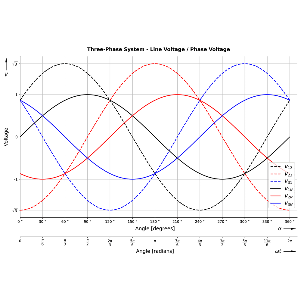
    Single-phase and three-phase AC drives are electrical systems used to control the speed and torque of AC (alternating current) motors. The primary difference between the two lies in the number of phases of the AC power supply they use and the motors they can drive.

    Single-Phase AC Drives:

    • Single-phase AC drives are designed to operate with a single-phase AC power supply, typically 120V or 230V in residential and light commercial applications.
    • They are commonly used for smaller loads, such as household appliances (e.g., fans, pumps, and some small machinery).
    • Single-phase motors have only one winding in the stator, which makes them less efficient for some applications and generally not suitable for high-power or industrial use.
    • Single-phase AC drives are less complex and generally more cost-effective for lower-power applications.

    Three-Phase AC Drives:

    • Three-phase AC drives are designed to work with a three-phase AC power supply, which is the standard in industrial and commercial settings.
    • They are used for a wide range of applications, from small motors to very high-power industrial machines.
    • Three-phase motors have three windings in the stator, which provides smoother operation and better performance, making them more efficient and suitable for high-torque and high-power applications.
    • Three-phase AC drives can provide more precise control over motor speed, torque, and direction and are commonly used in industrial automation and manufacturing.

    In summary, the main difference between single-phase and three-phase AC drives is the number of phases in the AC power supply they are designed for and the types of motors they can drive. Single-phase drives are typically used for smaller, low-power applications, while three-phase drives are used in a wide range of industrial and high-power settings.


  • What is the difference between a molded case circuit breaker and an earth leakage circuit breaker?

    What is the difference between a molded case circuit breaker and an earth leakage circuit breaker?

    The primary difference between a Molded Case Circuit Breaker (MCCB) and an Earth Leakage Circuit Breaker (ELCB) lies in their purpose and function in an electrical system:

    1. Function and Protection:
      • MCCB: It is designed to protect against overcurrents (both overload and short circuits). An MCCB will trip and disconnect the circuit when current exceeds the breaker’s rated capacity for a certain period, protecting wiring and equipment from damage.
      • ELCB: This breaker is specifically designed to protect against earth leakage or ground faults. It trips when it detects a leakage current to the ground, which could be a sign of a dangerous fault in the circuit, potentially preventing electric shocks.
    2. Sensitivity and Detection:
      • MCCB: It is sensitive to high current flow, but it does not specifically detect leakage or fault currents to the ground. Its tripping mechanism is based on thermal (for overload) and magnetic (for short circuit) properties.
      • ELCB: It is highly sensitive to leakage currents (even in milliamperes) and is designed to detect an imbalance between the live and neutral wires, indicating a fault.
    3. Usage and Applications:
      • MCCB: Commonly used in commercial and industrial electrical systems, where higher current ratings are needed. It is suitable for protecting electrical circuits, motors, and other equipment from overloading and short circuits.
      • ELCB: Ideal for residential, commercial, and outdoor applications, especially in wet areas or where there’s a higher risk of electrical shock. It’s used to add a layer of protection against electric shocks due to ground faults.
    4. Construction and Design:
      • MCCB: As the name suggests, it has a molded case which is a robust and insulated housing. It typically supports higher current ratings and might offer adjustable trip settings.
      • ELCB: It might be less robust compared to an MCCB and is more focused on detecting leakage currents rather than handling high power loads.
    5. Trip Mechanism:
      • MCCB: Uses thermal (for overload protection) and magnetic (for short circuit protection) trip mechanisms.
      • ELCB: Uses a differential current sensing mechanism to detect earth leakages.

    In summary, while MCCBs are primarily used for overcurrent protection (including overloads and short circuits) in higher-capacity circuits, ELCBs are used for sensitive detection and protection against earth leakage currents, providing safety against electrical shocks and some types of electrical fires. Both devices are essential in a comprehensive electrical protection strategy but serve different safety roles.

  • The Evolution of HMI Systems

    The Evolution of HMI Systems

    The evolution of Human Machine Interfaces (HMIs) has unfolded over decades, influenced and propelled by emerging technologies in electronics, telecommunication, and power engineering. Over the past 30 years, HMIs have served communication and control purposes, adapting to evolving technology.

    1980’s
    In the 1980s, process flow diagrams dominated monitoring processes, with large walls dedicated to such diagrams, adorned with gauges, indicators, and switches for a realistic representation of industrial processes.

    1990’s
    In the mid-1990s, PLC manufacturers gained ground, utilizing proprietary Operator Interface Terminals for control. The mid-1990s saw the introduction of PCs to manufacturing, necessitating a real-time Operating System. With the advent of Windows OS, Distributed Control Systems migrated to PCs. Platform-independent software was introduced, shifting HMI towards a software-centric technology. Simultaneously, ethernet revolutionized connectivity, transcending previous boundaries.

    2000’s
    In the early 2000s, HMIs capable of operating in hazardous areas were developed. Distributed control systems focused on HMI software and PC hardware. Touchscreens became prevalent in industrial technology, offering ease of use and reducing reliance on keyboards and mice.

    2010-Present
    The continual rise of new technologies ensures ongoing evolution in HMIs. Regardless of their future form, these devices will remain vital on the plant floor. The entry of multitouch video technologies, like tablets and smartphones, has once again transformed the role and scope of HMIs. Manufacturers now explore HMIs dependent on cross-platform technologies, such as HTML5, with Cloud Computing Servers at the backend, enabling access, monitoring, and control from any global location.

  • What are the benefits of a hybrid SiC module?

    What are the benefits of a hybrid SiC module?

    A hybrid SiC (Silicon Carbide) module refers to a power module that incorporates both SiC and other semiconductor materials, often silicon (Si). This combination leverages the strengths of SiC while mitigating potential drawbacks or cost considerations.

    Here are several benefits associated with hybrid SiC modules:

    1. Enhanced Efficiency:
      • SiC devices are known for their superior material properties, including a wide bandgap, which results in lower conduction and switching losses. Incorporating SiC components in a hybrid module can enhance overall efficiency, especially in high-frequency and high-temperature applications.
    2. Improved Thermal Performance:
      • SiC has better thermal conductivity compared to silicon, leading to improved thermal performance in power modules. The hybrid approach allows for optimized thermal management, combining the benefits of both materials to handle high-power densities more effectively.
    3. Optimized Cost:
      • While SiC devices can offer superior performance, they can be more expensive than traditional silicon devices. A hybrid SiC module allows designers to achieve a balance between performance and cost by strategically using SiC where it provides the most benefit and using silicon for less critical parts of the circuit.
    4. Compatibility with Existing Designs:
      • Hybrid SiC modules can be designed to be compatible with existing systems and infrastructure. This allows for easier integration into current applications without requiring a complete redesign of the entire system.
    5. Flexibility in Design:
      • Designers have the flexibility to choose where to implement SiC components based on the specific requirements of the application. This adaptability allows for customization and optimization for different parts of the power electronic circuit.
    6. Reduced Switching Losses:
      • SiC devices have faster switching speeds compared to traditional silicon devices. Hybrid SiC modules can capitalize on this advantage to reduce switching losses, leading to increased overall system efficiency.
    7. Higher Temperature Operation:
      • SiC devices can operate at higher temperatures compared to silicon devices. Hybrid SiC modules benefit from this characteristic, enabling applications in harsh environments or those that require high-temperature operation.
    8. High-Frequency Operation:
      • The fast switching speeds and low losses of SiC devices make hybrid SiC modules well-suited for high-frequency power electronic applications. This can be advantageous in areas such as power supplies, converters, and motor drives.
    9. Compact Size and Weight:
      • The improved performance and efficiency of SiC devices allow for the design of smaller and lighter power electronic systems. Hybrid SiC modules contribute to reducing the size and weight of the overall system.
    10. Reliability and Longevity:
      • SiC devices often exhibit improved reliability and longevity due to their robust material properties. This can lead to longer lifespan and reduced maintenance requirements in certain applications.

    While hybrid SiC modules offer various benefits, the specific advantages will depend on the application requirements and the way in which SiC is integrated into the overall power module design. Designers need to carefully consider factors such as cost, efficiency, thermal performance, and compatibility with existing systems when choosing between hybrid SiC and other power module options.

  • What is the most important thing to consider when selecting a regenerative blower?

    What is the most important thing to consider when selecting a regenerative blower?

    • Optimizing the efficiency of a regenerative blower requires proper system design. To reduce friction losses, one of the most crucial things to think about is using large-diameter plumbing. The piping ought to be one size bigger or at least the same size as the blower outlet port.
    • Blower performance is impacted by high altitude because of decreased airflow volume and pressure. By subtracting 4% of the volume and pressure for each 300 meters above sea level, one can easily estimate these losses. A blower intended to produce 100 cfm at sea level, for instance, will produce 96 cfm at 300 m above sea level.
    • Although performance varies, most regenerative blowers run on 50- or 60-cycle (Hz) power. Pressure and volume at 50 Hz are usually 16 percent lower than at 60 Hz.
    • Blowers take around ten seconds to start up to full speed. During this period, the power draw exceeds the specifications for full-load operation. Engineers advise sizing breakers using full-load amps and generators using starting watts.
    • Since the exhaust air temperature of regenerative blowers rises with increasing pressure, the heat of compression must be taken into account when designing piping systems. For instance, the exit air may be too hot for plastic pipe if a blower is run at a higher pressure because of high friction losses. In those situations, before connecting to the plastic piping system, longer lengths of metal pipe or sections of heat-dissipating pipe must be considered.
    • Lastly, always keep in mind the “laws” of fan performance. Rotational speed directly relates to variations in airflow. The square of the speed ratio causes a change in pressure. Additionally, horsepower varies with the speed ratio’s cube.
  • Choosing the right Instrumentation device for chemical and petrochemical manufacturing processes

    Choosing the right Instrumentation device for chemical and petrochemical manufacturing processes

    The safety and efficiency of any chemical or petrochemical manufacturing process depend largely on the selection of the right instrumentation. From reactor pressure transmitters to distillation column level measurement, state-of-the-art technology is essential for successful operations.

    The excellent reliability and measurement accuracy of the chosen measuring instruments enable you to increase process performance to guarantee maximum availability and optimize operating costs. Improving installations by using measuring instruments that are adapted and specific to your processes means optimizing energy and raw material consumption. The performance thus obtained generates significant savings in operating and investment costs: Enhanced reliability and improved process availability Accurate measurement for a quality finished product A low failure rate to increase equipment safety and integrity Long-term stability to reduce service intervals and maintenance costs Short response times to cope with rapid process variations A durable range to guarantee the longevity of the equipment

    Choose pressure and level transmitters designed for the toughest environments. Pressure measurement is used in many industrial process applications in the chemical and petrochemical industries (distillation columns, reactors, separators, etc.). These applications are characterized by very wide temperature and pressure ranges, and operate in highly corrosive media (chlorine, hydrochloric acid, sulfuric acid, etc.). Level, flow and density measurements are obtained in real time from information obtained from differential, gauge or absolute pressure measurements.

    Fuji Electric has developed a wide range of hydrostatic level transmitters with diaphragm seal(s) that are resistant to the most severe chemical attack. They are ideal for the storage and supply of raw materials for processes (vats and buffer tanks, storage of solvents, toxic liquids, ammonia, chlorine, etc.). Our diaphragm seals pressure transmitters are temperature-compensated to ensure accurate, reliable measurements in all ambient and process conditions. The materials used in their manufacture guarantee a long lifespan (stainless steel, Hastelloy C®, Tantalum, Monel®, etc.).

  • How do I choose the right UPS?

    How do I choose the right UPS?

    Choosing the right Uninterruptible Power Supply (UPS) involves assessing your power protection needs carefully and considering several key factors.

    Here’s a comprehensive guide to help you select the most suitable UPS for your requirements:

    1. Assess Your Power Needs
    • Calculate Total Wattage: Sum up the wattage of all devices you plan to connect to the UPS. This information can typically be found on the devices’ power supplies or user manuals.
    • Consider Future Expansion: Allow for additional capacity if you anticipate adding more devices in the future. A good rule of thumb is to add 20-25% to your current power needs to accommodate growth.
    1. Determine Required Runtime
    • Short vs. Long Runtime: Decide how long you need your equipment to run on battery power during a power outage. Shorter runtimes may suffice for saving work and shutting down equipment safely, whereas longer runtimes may be needed for critical equipment in data centers or medical facilities.
    • Battery Capacity and Expandability: Check if the UPS can support additional external battery packs for extended runtime, especially important for critical systems that require longer backup times.
    1. Understand UPS Topologies
    • Standby (Off-Line): Suitable for home or office environments where occasional power fluctuations occur.
    • Line-Interactive: Offers voltage regulation for environments with more frequent voltage fluctuations, without using the battery.
    • Double-Conversion (On-Line): Provides the highest level of protection by constantly converting power, ideal for sensitive and critical equipment.
    1. Evaluate Power Quality
    • Power Conditions: If you’re in an area with poor power quality, frequent outages, or significant voltage fluctuations, consider a Line-Interactive or Double-Conversion UPS for better protection.
    • Sensitivity of Equipment: Highly sensitive equipment, such as servers, networking devices, or medical equipment, benefits from the clean and consistent power supplied by a Double-Conversion UPS.
    1. Consider Features and Connectivity
    • Management Software: Look for UPS models that come with management software for monitoring power conditions, controlling the UPS remotely, and gracefully shutting down connected equipment.
    • Connectivity Options: Check for USB, serial, or network connectivity for integration with your existing setup and for easy management.
    1. Assess Installation and Maintenance
    • Physical Size: Make sure you have enough space for the UPS, considering both its physical dimensions and ventilation requirements.
    • Maintenance Requirements: Understand the maintenance needs, such as battery replacement and service checks. Some UPS models offer hot-swappable batteries for easy maintenance without power interruption.
    1. Budget and Brand Reputation
    • Cost: Balance your budget with your needs. While higher-end models offer better protection, they also come at a higher price.
    • Brand and Warranty: Consider reputable brands that offer solid warranties and customer support. Reviews and industry recommendations can help narrow down your choices.

    By carefully considering these aspects, you can choose a UPS that not only meets your current needs but also accommodates future expansion and provides reliable power protection for your valuable equipment.

  • What are earth leakage circuit breakers?

    What are earth leakage circuit breakers?

    Earth Leakage Circuit Breakers (ELCBs) are safety devices used in electrical installations to prevent electric shocks and electrical fires caused by ground faults.

    Here’s a detailed explanation of their characteristics and function:

    1. Purpose: ELCBs are designed to detect small stray voltages on the metal enclosures of electrical equipment and interrupt the circuit if a dangerous voltage is detected. They offer protection against earth leakage or ground fault, which occurs when there is an unintentional electrical connection between a live conductor and the ground.
    2. Operation Principle: The ELCB monitors the current balance between two or more conductors (typically live and neutral). In a healthy circuit, the current flowing through these conductors is equal. If there is a leakage to the ground, this balance is disturbed, and the ELCB trips, disconnecting the circuit.
    3. Sensitivity: ELCBs are sensitive to small leakages, typically in the range of milliamperes, and they respond quickly to prevent electrocution and fire hazards.
    4. Types:
      • Voltage-Operated ELCB: This older type of ELCB detects a voltage on the earth wire relative to the ground and disconnects if this voltage exceeds a set value. They are less common now and have been largely replaced by RCCBs.
      • Current-Operated ELCB (now more commonly known as Residual Current Circuit Breaker or RCCB): This type detects an imbalance in the live and neutral currents. It’s more effective as it does not rely on the connection to the actual earth but on the balance between live and neutral wires.
    5. Applications: ELCBs are commonly used in residential, commercial, and industrial settings, especially in wet areas like bathrooms and kitchens, outdoor circuits, and in environments where electrical equipment is more susceptible to damage or moisture, which could lead to ground faults.
    6. Difference from MCBs and MCCBs: Unlike Miniature Circuit Breakers (MCBs) and Molded Case Circuit Breakers (MCCBs) which protect against overcurrent and short circuits, ELCBs specifically protect against earth leakage currents.
    7. Reset Capability: Like MCBs and MCCBs, ELCBs can be manually reset after tripping, making them reusable and convenient for maintaining circuit protection.

    LCBs play a crucial role in modern electrical safety, providing an essential layer of protection against electrical shocks and fires due to ground faults. Their use is particularly important in circuits where the risk of electric shock is high.