
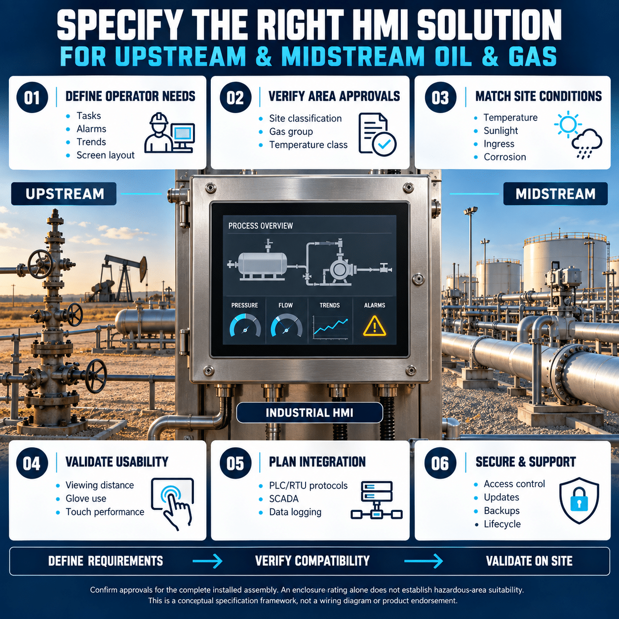
Upstream and midstream oil and gas operations depend on reliable access to process information. Operators need to monitor pressures, flows, temperatures, tank levels, motor loads, valve positions and equipment status across facilities that may be remote, unmanned or exposed to harsh environmental conditions.
A human machine interface, or HMI, gives operators a local point for viewing that information and interacting with the control system. The right HMI can simplify operations, accelerate troubleshooting and improve visibility into critical equipment. The wrong HMI can create communication problems, cybersecurity risks or reliability issues in the field.
Specifying the right solution requires more than selecting a screen size. Engineers should consider the process, location, connected equipment, hazardous-area requirements, environmental exposure, network architecture and long-term support strategy.
Start by defining the HMI’s role
An HMI is usually an operator interface, not the primary process controller. A programmable logic controller, remote terminal unit or dedicated equipment controller should continue to run essential logic if the HMI is unavailable.
Define exactly what the HMI must do.
Common upstream and midstream functions include:
- Starting and stopping equipment
- Changing authorized setpoints
- Displaying pressures, temperatures, flow rates and levels
- Monitoring pumps, compressors and AC drives
- Showing valve position and command status
- Presenting current and historical alarms
- Displaying operating trends
- Recording operator actions
- Managing equipment recipes or configuration sets
- Supporting commissioning and maintenance
- Providing access to equipment diagnostics
- Exchanging selected data with supervisory systems
The requirements for a pump skid are different from those of a compressor station or pipeline terminal. A small package may need only a few screens and one controller connection. A large station may require access to multiple PLCs, drives, meters and analyzers.
Create a functional description and point list before selecting the HMI hardware.
Identify the application
The application determines the required performance, connectivity and durability.
Typical upstream applications include:
- Wellhead control
- Electric submersible pump systems
- Pump-jack control
- Produced-water systems
- Chemical injection skids
- Test and measurement equipment
- Separation equipment
- Compressor packages
- Drilling support equipment
Typical midstream applications include:
- Pipeline pump stations
- Compressor stations
- Tank farms
- Storage terminals
- Metering skids
- Loading and unloading systems
- Natural gas processing
- Leak-detection support systems
- Filtration and separation packages
- Vapor recovery units
Document the number of assets, control loops, alarms and operator commands associated with the application. This helps establish the required screen size, memory, processing capability and communications capacity.
Determine the hazardous-area requirements
Oil and gas facilities frequently contain classified areas. The HMI and its installation must be suitable for the exact location.
Identify:
- Classification system
- Class, division or zone
- Gas group
- Temperature class
- Ambient temperature range
- Required protection method
- Applicable national and local codes
- Authority having jurisdiction
- Certification required by the end user
Do not assume that an industrial HMI is approved for every classified location. Hazardous-area approval may apply only to particular models, configurations and installation conditions.
Possible installation strategies include:
- Mounting an approved HMI directly in the classified area
- Installing the HMI in a purged or pressurized enclosure
- Mounting it inside a certified explosion-protected enclosure
- Placing the HMI outside the classified area
- Using a remote display or web interface from a safe location
Verify the certification of the complete assembly, including enclosure, glands, wiring, power supply and communications equipment.
Some MONITOUCH configurations have certifications for specific hazardous-location applications, but the exact model and approval must be confirmed from current product documentation. Approval of one model should never be applied to the entire product family.
Match the HMI to the environment
Outdoor and field-mounted equipment may face conditions that are very different from those in a control room.
Evaluate:
- Minimum and maximum temperature
- Direct solar heating
- Humidity
- Condensation
- Rain and water spray
- Dust and sand
- Salt exposure
- Hydrogen sulfide
- Corrosive gases
- Ultraviolet radiation
- Vibration and shock
- Altitude
- Electromagnetic interference
The panel’s front-face rating applies only when it is installed correctly with the specified gasket and mounting hardware. The rear of the HMI usually depends on the surrounding enclosure for protection.
An HMI with an IP66 or Type 4X front panel may still require:
- A sunshield
- Enclosure heating
- Air conditioning
- A heat exchanger
- Anti-condensation control
- Corrosion-resistant hardware
- A protective overlay
- A suitably rated enclosure
Operating temperature should be evaluated inside the enclosure, not only at the weather station. Solar loading and heat from power supplies, radios and controllers can raise the internal temperature significantly.
Also confirm whether the HMI is permitted in an atmosphere containing corrosive gas or conductive dust. A suitable external enclosure may be necessary even when the front panel has a strong water and dust rating.
Choose the right display size
Screen size should reflect how the HMI will be used.
A compact display may be sufficient for:
- One pump
- A metering skid
- A chemical injection package
- A local valve station
- A simple test fixture
A larger display may be appropriate for:
- Compressor stations
- Multiple pump trains
- Tank terminals
- Gas-processing packages
- Systems with detailed trends
- Applications requiring several process areas on one overview
Consider:
- Viewing distance
- Amount of information shown
- Required trend detail
- Available panel space
- Operator gloves
- Screen brightness
- Sunlight readability
- Touch-target size
- Number of languages
- Need for physical function keys
Avoid selecting a small display and then crowding it with dozens of values. Operators should be able to recognize the current process state quickly.
A good screen hierarchy normally includes:
- Facility or package overview
- Equipment detail
- Process trends
- Alarm summary
- Maintenance diagnostics
- Configuration screens
Select the touchscreen technology carefully
Industrial HMIs commonly use resistive or projected-capacitive touchscreens.
Resistive touchscreens
A resistive touchscreen responds to pressure. It can often be used with many types of gloves and may be a practical choice for field technicians.
Projected-capacitive touchscreens
A projected-capacitive screen can provide responsive operation and a modern interface. Glove compatibility depends on the glove material, thickness and panel settings.
Test the intended gloves before finalizing the selection. Oil, water, dust and cleaning methods can also affect touch performance.
Critical actions should require confirmation. An accidental touch should not stop a compressor, open a valve or change a critical pressure setpoint.
Verify every communications requirement
An Ethernet port does not guarantee compatibility with every connected device. The HMI must support the required protocol and have the correct driver for each controller.
Create a communications matrix that identifies:
- Device manufacturer
- Model number
- Protocol
- Physical interface
- Read and write points
- Polling rate
- Data format
- Alarm requirements
- Redundancy requirements
Potential connections include:
- PLCs
- Remote terminal units
- AC drives
- Flow computers
- Pressure transmitters
- Flow meters
- Temperature controllers
- Motor protection relays
- Power meters
- Gas analyzers
- Remote input and output
- Supervisory control systems
Common interfaces can include serial communications, industrial Ethernet and fieldbus networks. Legacy assets may require RS-232, RS-422 or RS-485, while newer systems may use Ethernet-based protocols.
Fuji Electric MONITOUCH HMIs support connections to equipment from multiple manufacturers. The appropriate driver and option hardware should be confirmed for each device.
Determine how many devices the HMI must manage
A single HMI may need to communicate with several controllers or intelligent devices.
Fuji Electric MONITOUCH solutions can support multidrop and multiple-device communication, including configurations that allow one interface to collect and display information from several connected systems.
Before consolidating devices onto one panel, evaluate:
- Total point count
- Number of simultaneous connections
- Required response time
- Network bandwidth
- Polling frequency
- Failure behavior
- Cybersecurity zones
- Maintenance ownership
Consolidation can reduce wiring and panel space, but it can also create a larger operational dependency. If one HMI is the only local interface for several critical assets, consider whether a failure would impede operation or maintenance.
Separate local control from supervisory monitoring
Upstream and midstream systems often include several layers:
- Field instruments
- Local equipment controllers
- PLCs or RTUs
- Local HMIs
- Station control systems
- SCADA
- Enterprise data systems
- Cloud or analytics platforms
Define which layer owns each command.
For example:
- The PLC may own automatic control.
- The local HMI may provide maintenance commands.
- SCADA may issue remote operating requests.
- A central system may collect historical data without control authority.
The interface should clearly display whether equipment is in local, remote, manual or automatic mode. It should also show why a command is unavailable.
Conflicting commands can occur when local and remote systems write to the same point without a defined priority. Establish command arbitration in the control logic and document it in the operating philosophy.
Design for remote locations
Many oil and gas assets are geographically dispersed and may have limited communications bandwidth.
Remote sites can use:
- Licensed radio
- Cellular networks
- Microwave links
- Satellite
- Fiber
- Private Ethernet
- Virtual private networks
The HMI should continue to operate locally when the wide-area connection is lost. Essential control should not depend on continuous access to a remote server or cloud service.
For constrained links, consider:
- Polling frequency
- Amount of data transferred
- Store-and-forward behavior
- Local alarm history
- Local trend storage
- Communication retries
- Time synchronization
- Data compression
- Remote-update size
Connection loss should generate a clear status indication without creating an alarm flood.
Specify alarm management
An HMI should help operators recognize abnormal conditions and respond correctly.
Each alarm should have:
- A clear description
- Priority
- Timestamp
- Process location
- Equipment identifier
- Current value
- Alarm limit
- Acknowledgment state
- Suggested operator response
Separate alarms from routine status messages. A pump being off because it is not required should not be presented like a pump that failed during a start command.
Useful features include:
- Current alarm list
- Historical alarm log
- Filtering by unit or priority
- First-out indication
- Audible annunciation
- Shelving under controlled conditions
- Operator acknowledgment records
- Alarm frequency analysis
The HMI should not be the only location where critical protective actions are implemented. Shutdowns and safety functions belong in appropriately designed control or safety systems.
Include trends and historical data
Trend information helps operators diagnose unstable processes and intermittent equipment problems.
Useful upstream and midstream trends can include:
- Suction and discharge pressure
- Flow rate
- Tank level
- Temperature
- Valve command and position
- Motor current
- Drive speed
- Compressor vibration
- Filter differential pressure
- Separator pressure
- Chemical injection rate
- Equipment runtime
Define:
- Sampling interval
- Storage duration
- Number of tags
- File format
- Export method
- Time synchronization
- Backup method
- Behavior when storage is full
A short sampling interval can support troubleshooting but consumes more storage. Long-term operational analysis may need only slower data.
Fuji Electric MONITOUCH systems can support data logging, operation logs and storage of information in formats such as CSV, depending on the selected model and configuration.
Use operation logs for accountability
Operator action logs can record:
- Start and stop commands
- Setpoint changes
- Mode changes
- Alarm acknowledgments
- Recipe selection
- Login activity
- Maintenance actions
This information can help determine what happened before a process upset or equipment trip.
Use individual accounts where practical. Shared passwords make it difficult to establish who performed an action.
Logs should include reliable timestamps. Coordinate the HMI clock with the PLC, SCADA and other event-recording systems so that records can be compared accurately.
Apply role-based access
Not every user should have the same authority.
A practical structure might include:
- View-only user
- Operator
- Maintenance technician
- Controls engineer
- Administrator
Operators may need to start equipment and adjust routine setpoints within approved limits. Maintenance personnel may need access to manual controls and diagnostics. Engineering functions should have stronger protection.
Security settings should control:
- Screen access
- Command authority
- Setpoint ranges
- Recipe changes
- Alarm shelving
- File export
- Network configuration
- Application modification
- Remote access
Do not rely on a hidden screen as a security control. Use proper authentication and authorization.
Treat cybersecurity as a design requirement
An HMI connected to a control network is part of the operational technology attack surface.
The specification should address:
- Default passwords
- Account management
- Network segmentation
- Firewall rules
- Remote-access methods
- Unused services
- Removable media
- Application backups
- Firmware management
- Security logging
- Physical access
- Incident recovery
Separate operational technology networks from business networks. Data exchange between them should pass through controlled and monitored interfaces.
Remote support should use an approved access path with authentication, encryption and session control. Avoid directly exposing an HMI to the public internet.
Wireless communications should be enabled only when required and approved by the facility’s security architecture.
Evaluate OPC UA and MQTT use carefully
Higher-level connectivity may be useful when operating data needs to reach historians, analytics systems or enterprise applications.
Fuji Electric’s MONITOUCH X1 Series supports OPC UA server and client functions and can act as a gateway between field equipment and higher-level systems. It also supports MQTT connectivity for suitable data-sharing applications.
These capabilities can help standardize data exchange, but they should not bypass the site’s control and cybersecurity architecture.
Before enabling higher-level connectivity, define:
- Data ownership
- Read-only and write permissions
- Security certificates
- Encryption
- Broker or server location
- Store-and-forward behavior
- Connection-loss response
- Patch responsibility
- Long-term support
Cloud connectivity should never become a prerequisite for safe local operation.
Verify power requirements
Remote oil and gas installations may have limited or unstable power.
Determine:
- Available voltage
- AC or DC supply
- Voltage tolerance
- Power consumption
- Inrush current
- Grounding
- Surge protection
- Backup power
- Required ride-through time
A 24 VDC HMI may integrate well with control-system batteries or a DC uninterruptible power supply.
The control logic should continue to operate safely if the HMI loses power. When power returns, the HMI should reconnect automatically and display the actual process state.
Address surge and electrical noise
Oil and gas sites may contain long cable runs, large motors, AC drives, contactors and outdoor circuits exposed to lightning-related surges.
Protect the HMI and its communications with:
- Correct grounding and bonding
- Suitable surge-protective devices
- Shielded communications cable
- Proper shield termination
- Separation of power and signal wiring
- Fiber-optic links where appropriate
- Isolated communication interfaces
- Stable control power
Do not route low-level communication wiring alongside motor leads or drive output cables.
Communication problems are often caused by installation details rather than the HMI itself. Verify topology, termination, biasing and grounding for every serial network.
Select a suitable MONITOUCH family
Fuji Electric offers several HMI platforms for different levels of complexity.
MONITOUCH TECHNOSHOT
TECHNOSHOT can suit basic equipment and packaged systems that need clear visualization, Ethernet connectivity and straightforward installation.
Potential applications include:
- Pump skids
- Chemical injection packages
- Small metering systems
- Local equipment panels
- Auxiliary systems
MONITOUCH V9
The V9 Series supports applications requiring multiple communications interfaces, data storage, logging and a broad range of display sizes.
Potential applications include:
- Test equipment
- Compressor packages
- Pump systems
- Metering skids
- Multidevice panels
- Retrofit projects
MONITOUCH V10
The V10 Series provides higher processing performance for applications with complex graphics, high point counts, multiple connections or demanding screen-response requirements.
Potential applications include:
- Compressor stations
- Pipeline facilities
- Large process packages
- Tank terminals
- Systems with extensive trends and alarms
Applicable V10 models provide features such as high-speed processing, Ethernet, serial communications, removable storage and front-panel environmental protection. Exact specifications vary by model.
MONITOUCH X1
The X1 Series combines HMI functions with a Windows-based platform and broader IT connectivity.
It may suit applications requiring:
- OPC UA
- MQTT
- Edge data processing
- Windows applications
- Connection to host systems
- Advanced data visualization
The additional flexibility of a Windows-based system requires an appropriate patching, backup and cybersecurity plan.
Consider migration and lifecycle support
Oil and gas assets may remain in service for decades. HMI selection should account for future replacement and software support.
Confirm:
- Configuration software availability
- License requirements
- Supported engineering-computer operating systems
- Application backup procedures
- Source-file ownership
- Firmware availability
- Replacement-model strategy
- Panel-cutout compatibility
- Spare-unit availability
- Technical support
- Documentation
- Long-term protocol support
A replacement HMI should be recoverable from a documented backup without depending on one technician’s laptop.
Maintain an asset record containing:
- Model and serial number
- Firmware version
- Application version
- Network settings
- User-account procedure
- Backup location
- Connected-device list
- Required option modules
- Date of last update
Design screens for abnormal situations
Operators often need the HMI most when something has gone wrong.
Screens should answer:
- What happened?
- Which equipment is affected?
- Is the process safe?
- What interlock is preventing operation?
- What changed before the event?
- What action is permitted?
- Who has control authority?
Use color consistently and reserve strong colors for conditions that require attention. Do not use color as the only indicator. Pair it with text, symbols and state labels.
Show both commands and feedback. For example, display valve command and actual position together. A pump graphic should distinguish among stopped, running, commanded to run, failed to start and unavailable.
Test the complete solution
Commissioning should verify more than screen appearance.
Test:
- Every command
- Every status point
- Scaling and engineering units
- Alarm limits and priorities
- Alarm acknowledgment
- User-access levels
- Operation logs
- Trend accuracy
- Time synchronization
- Loss of each communications link
- Power interruption and recovery
- Remote-access behavior
- Controller restart
- HMI restart
- Storage failure
- Application backup and restoration
Hazardous-area installation details should be inspected against the approved drawings and product conditions of use.
The final handover should include:
- Editable application files
- Compiled runtime files
- Communications settings
- User-management procedure
- Firmware information
- Network architecture
- Point list
- Alarm list
- Backup and restore instructions
- Spare-parts recommendations
HMI specification checklist
Before selecting an HMI for an upstream or midstream application, confirm:
- What process and equipment will the HMI support?
- Is it a local interface, supervisory interface or edge platform?
- What functions and commands are required?
- How many devices and points will be connected?
- Which exact protocols and drivers are needed?
- Is the installation in a classified area?
- What hazardous-location certification is required?
- What environmental conditions must the HMI withstand?
- What screen size and touchscreen technology are appropriate?
- Will operators wear gloves?
- What alarm, trend and logging functions are required?
- How will local and remote command authority be coordinated?
- What happens if the wide-area network is lost?
- What user roles and audit records are required?
- How will the HMI be segmented and secured?
- Is OPC UA, MQTT or another higher-level interface required?
- What power and surge protection are available?
- How will applications and settings be backed up?
- What is the replacement and lifecycle strategy?
- Has the complete system been functionally tested?
Specify the HMI as part of the control system
The right HMI is not simply a display mounted on a panel. It is an operational interface between personnel, controllers, field equipment and supervisory systems.
For upstream and midstream oil and gas applications, the HMI must match the process, withstand the environment, communicate with every required device and fit within the site’s safety and cybersecurity architecture.
Fuji Electric’s MONITOUCH portfolio includes basic operator panels, high-performance HMIs and Windows-based edge platforms. By defining the application, hazardous-area requirements, communications architecture and operator needs before selecting a model, engineers can create an HMI solution that supports reliable operation, faster troubleshooting and long-term maintainability.