
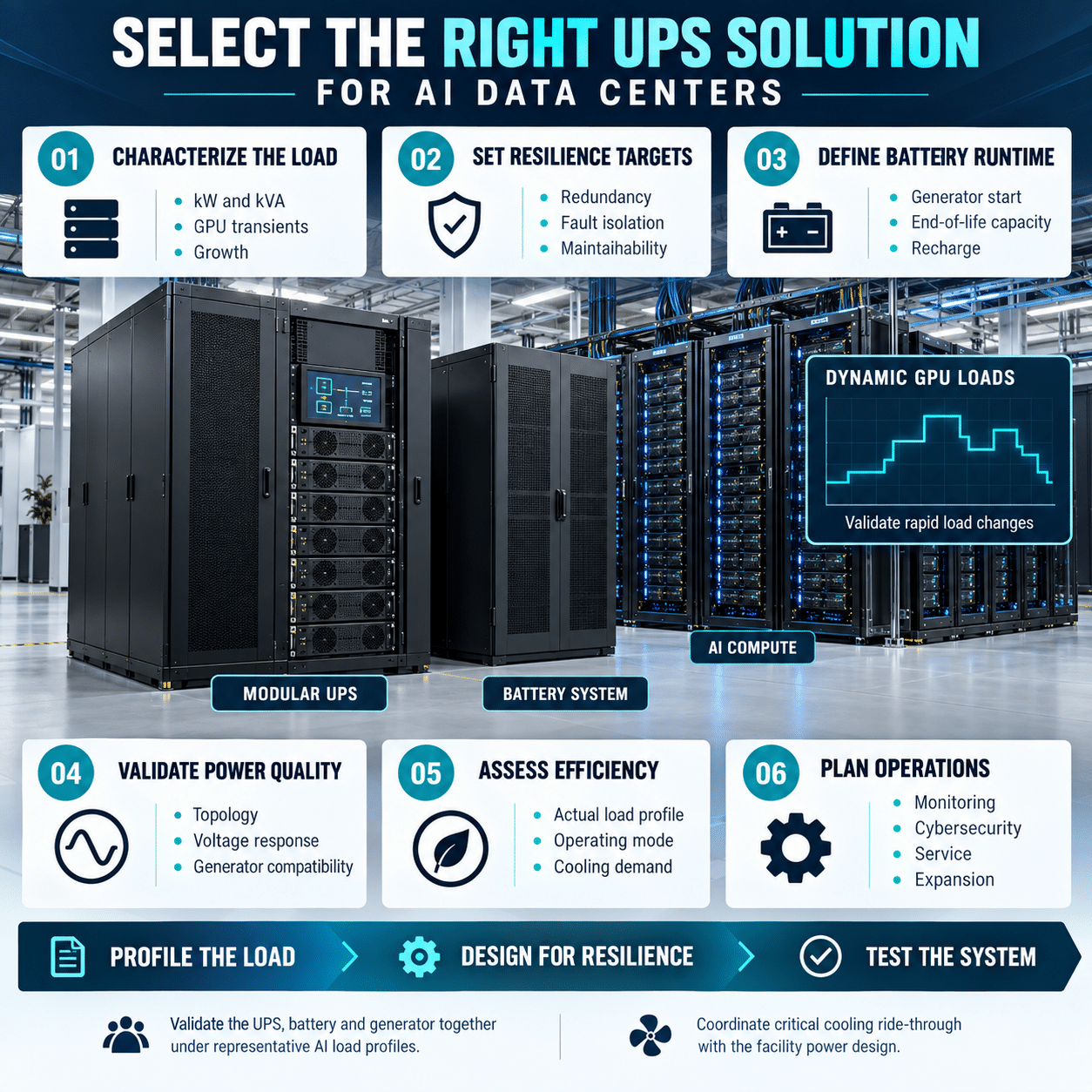
Artificial intelligence is changing the electrical profile of the data center. High-density GPU clusters can concentrate large amounts of computing power into relatively small spaces, while workload scheduling can create rapid changes in facility demand.
The uninterruptible power supply, or UPS, must protect these loads without becoming a constraint on capacity, efficiency or future growth. A solution sized only from today’s nameplate values may be difficult to expand. A system designed only for peak efficiency may not provide the resilience, dynamic performance or maintainability required by the facility.
Selecting the right UPS requires a complete evaluation of the load, power architecture, redundancy strategy, runtime, cooling system and operating plan.
Begin with the critical load
The UPS should be sized from the load it must support, not from the building’s total electrical service.
Identify which systems require uninterrupted power:
- GPU and CPU servers
- Storage
- Network equipment
- Rack power distribution
- Controls
- Security systems
- Cooling controls
- Coolant distribution units
- Pumps required for ride-through
- Monitoring and communications
- Other essential infrastructure
Some cooling equipment may be supported by the UPS, while large chillers and pumps may transfer directly to standby generation. That decision affects both UPS capacity and the thermal response of the data hall.
Separate the following values:
- Installed load
- Present operating load
- Contracted IT load
- Design load
- Future expansion load
- Temporary commissioning load
- Redundant capacity
This prevents growth allowance from being confused with operational redundancy.
Size in both kilowatts and kilovolt-amperes
UPS capacity is commonly expressed in both kW and kVA.
Kilowatts represent real power. Kilovolt-amperes represent apparent power, which includes the effect of power factor.
The relationship is:
[
\text{kW} = \text{kVA} \times \text{Power Factor}
]
Modern server power supplies often operate with a power factor close to unity, but the complete load should still be evaluated. Cooling equipment, legacy devices and lightly loaded power supplies can change the system power factor.
The UPS must have enough kW capacity for real power and enough kVA capacity for total current.
Review:
- Full-load power factor
- Part-load power factor
- Leading or lagging operation
- Harmonic current
- Crest factor
- Phase balance
- Neutral current
- Expected load changes
Do not assume that every AI rack presents an identical electrical profile.
Understand the dynamic behavior of AI loads
AI computing loads can change quickly as accelerators begin or complete computational work. Workload orchestration may also shift jobs among clusters or data halls.
Potential effects include:
- Rapid load steps
- Repetitive power variation
- Short-duration peaks
- Changes in power factor
- Voltage regulation challenges
- Increased thermal transients
The UPS should maintain stable output voltage during these changes without unnecessary battery operation or bypass transfer.
Ask the server and rack-system suppliers for:
- Maximum steady-state power
- Short-duration peak power
- Load-step magnitude
- Ramp rate
- Duration of peaks
- Power-factor range
- Harmonic-current data
- Ride-through capability
- Power-capping behavior
Use measured data from representative equipment whenever possible. Nameplate ratings often describe maximum input capability rather than typical operation.
Fuji Electric’s UPS7400WX-T3U is designed to limit output-voltage variation to less than 3% during a 100% load step under its specified conditions, without using the battery. Dynamic specifications such as this should be compared with the actual load profile.
Select the appropriate topology
Online double-conversion UPS
An online double-conversion UPS converts incoming AC power to DC and then converts it back to regulated AC.
This architecture provides:
- Continuous voltage regulation
- Frequency regulation
- Isolation from many utility disturbances
- Battery integration through the DC bus
- No normal transfer delay when input power fails
It is commonly used for critical AI computing because the inverter continuously supplies the load.
High-efficiency operating mode
Some UPS systems offer an economy or high-efficiency mode that supplies the load through a bypass path when utility conditions are acceptable.
This can reduce conversion loss, but the designer must evaluate:
- Transfer time
- Utility power quality
- Load sensitivity
- Voltage and frequency limits
- Harmonic performance
- Surge exposure
- Operating-mode controls
- Risk policy
High-efficiency mode should not be treated as equivalent to online double-conversion operation. The two modes provide different levels of power conditioning.
Fuji Electric’s UPS7400WX-T3U provides online double-conversion operation and a selectable high-efficiency mode. Published performance reaches approximately 97% in normal operation at common load levels and up to 99% in high-efficiency mode under specified conditions.
Evaluate efficiency across the real load profile
Peak efficiency is only one data point.
AI facilities may initially operate below design capacity because:
- Compute equipment is installed in phases.
- Redundant systems divide the load.
- Space is reserved for future clusters.
- Workloads vary over time.
- Capacity is intentionally held in reserve.
Request efficiency at:
- 10% load, if available
- 25% load
- 50% load
- 75% load
- 100% load
A flat efficiency curve can be more valuable than a slightly higher peak.
UPS loss can be estimated as:
Ploss = Pout (1/ η – 1)
where:
- Ploss is UPS power loss
- Pout is output power
- η is efficiency expressed as a decimal
Every kilowatt lost by the UPS becomes heat that must be removed from the electrical space. Include both direct electrical loss and cooling energy in the lifecycle analysis.
Fuji Electric uses advanced three-level conversion, reverse-blocking IGBT technology and SiC components in applicable UPS systems to reduce conversion loss.
Choose the redundancy architecture
The appropriate redundancy level depends on the business impact of a power interruption.
Common architectures include:
N
The system has enough capacity to support the design load but no redundant capacity.
N+1
One additional module or unit is available beyond the capacity required for the load.
N+2
Two additional modules or units are available.
2N
Two independent systems can each support the full load.
2N+1
Each side includes additional redundant capacity.
Distributed redundancy
Multiple systems share the load through a design intended to tolerate selected failures without duplicating every component.
The notation alone does not prove resilience. Review the entire power path, including:
- Utility feeds
- Switchgear
- UPS modules
- Batteries
- Bypass source
- Output switchboards
- Distribution buses
- Rack power supplies
- Controls
- Cooling support
A nominally redundant UPS system can still contain common points of failure.
Distinguish module redundancy from system redundancy
A modular UPS can include multiple power modules within one cabinet or system.
Module redundancy can allow the UPS to continue operating after one module is unavailable. It can also simplify capacity expansion.
System redundancy uses separate UPS systems and power paths.
These approaches address different risks.
When evaluating modular architecture, ask:
- Can a module be isolated safely?
- Can it be replaced while the system supports the load?
- Are controls redundant?
- Are cooling fans redundant?
- Is the static bypass shared?
- Is the battery shared?
- What happens during module maintenance?
- Can modules operate at unequal loading?
- How is firmware managed?
- Is expansion possible without shutdown?
Fuji Electric’s UPS7400WX-T3U uses 330 kVA power modules and supports configurable capacity and module redundancy within the product family. Parallel systems can provide additional capacity and architectural flexibility.
Plan for phased growth
AI infrastructure can expand rapidly, but building the entire final UPS capacity on day one may reduce part-load efficiency and increase capital cost.
A scalable design can align UPS deployment with actual compute growth.
Evaluate:
- Initial critical load
- Capacity added per phase
- Maximum system size
- Module increment
- Parallel-system limit
- Switchgear capacity
- Battery expansion
- Cable and busway ratings
- Cooling capacity
- Floor space
- Future maintenance access
Reserve the infrastructure needed for expansion, even if the initial UPS installation is smaller.
This may include:
- Switchgear sections
- Conduits
- Cable pathways
- Busway capacity
- Battery space
- Cooling connections
- Control-network ports
- Structural support
Expansion should not require exposing the existing critical load to unnecessary risk.
Avoid chronic oversizing
Oversizing may appear conservative, but it can create disadvantages:
- Lower operating load percentage
- Reduced efficiency
- Higher capital cost
- Larger footprint
- More cooling equipment
- More batteries
- Higher maintenance cost
Separate four concepts:
- Present operating capacity
- Forecast growth
- Redundant capacity
- Temporary overload capability
They should not be combined into one arbitrary oversizing factor.
Modular architecture can reduce the need to install unused conversion capacity years before it is required.
Verify overload capability
The UPS must support credible temporary overloads without transferring unexpectedly to bypass or dropping the load.
Review performance at:
- 105% load
- 110% load
- 125% load
- 150% load
- Short-duration peak load
- Repetitive peak load
- High ambient temperature
The time allowed at each overload level matters.
Fuji Electric’s UPS7400WX-T3U lists overload capability of 125% for 10 minutes and 150% for 1 minute under specified conditions.
Overload capacity should not be used as permanent design capacity. It provides operating margin for temporary conditions and fault coordination.
Evaluate short-circuit performance
A UPS inverter cannot usually supply the same fault current as a utility transformer.
This affects downstream protection.
Verify:
- Inverter fault-current magnitude
- Duration of fault current
- Current-limiting behavior
- Static-bypass response
- Breaker trip characteristics
- Fuse characteristics
- Selective coordination
- Arc-flash calculations
- Fault clearing on battery
- Ground-fault behavior
A downstream breaker selected for a utility-fed system may not trip promptly when supplied only by the UPS inverter.
Coordinate the complete system under:
- Normal utility operation
- Battery operation
- Bypass operation
- Generator operation
- Maintenance configuration
Do not assume that a high bypass fault rating describes the inverter’s output capability.
Select the battery or energy-storage technology
The UPS energy-storage system must bridge the interval between utility loss and the restoration of a stable source.
Common options include:
- Valve-regulated lead-acid batteries
- Lithium-ion batteries
- Flywheels
- Other approved energy-storage systems
Valve-regulated lead-acid batteries
Potential advantages include:
- Established technology
- Broad service experience
- Familiar maintenance practices
- Wide availability
Considerations include:
- Larger footprint
- Greater weight
- Temperature sensitivity
- Periodic replacement
- Ventilation and monitoring
Lithium-ion batteries
Potential advantages include:
- Smaller footprint
- Lower weight
- Longer service-life potential
- Faster recharge capability
- Integrated battery management
Considerations include:
- Higher initial cost
- Battery-management-system integration
- Fire protection
- Code compliance
- Cell chemistry
- Thermal management
- End-of-life planning
Flywheels
Potential advantages include:
- High cycle capability
- Compact short-duration support
- Reduced dependence on chemical batteries
- Long service-life potential
Considerations include:
- Shorter practical runtime
- Mechanical-system requirements
- Standby losses
- Maintenance approach
The UPS7400WX-T3U supports energy-storage options including VRLA batteries, lithium-ion batteries and flywheels in applicable configurations.
Determine the correct runtime
Longer battery runtime is not always better.
Runtime should be based on:
- Generator start time
- Generator synchronization
- Fuel-system reliability
- Transfer sequence
- Cooling ride-through
- Shutdown time
- Utility-reliability history
- Local regulations
- Business-continuity strategy
Common runtime strategies include:
- Short ride-through until generators stabilize
- Enough time for an orderly workload shutdown
- Extended runtime where generation is unavailable
- Tiered runtime for different load classes
AI servers may continue producing substantial heat during a power event. If cooling support is not maintained, a long electrical runtime may not provide useful operational continuity.
Coordinate UPS runtime with:
- CDU operation
- Cooling pumps
- Air handlers
- Chilled-water storage
- Generator-backed chillers
- Thermal ride-through
- IT workload shedding
Electrical and thermal resilience must be designed together.
Include battery aging and recharge
Battery capacity declines with:
- Age
- Temperature
- Cycling
- High discharge rate
- Manufacturing variation
- Maintenance condition
Apply the appropriate aging, temperature and design margins.
Also evaluate recharge time. After one outage, the system may need to withstand another event before the batteries have fully recovered.
Ask:
- What recharge current is available?
- Does charging reduce UPS load capacity?
- Can recharge be limited on generator power?
- How long does full recharge take?
- How is battery state of health measured?
- What alarms are available?
- How are weak strings identified?
Battery monitoring should be integrated into the facility’s maintenance program.
Coordinate with standby generators
The UPS and generator must operate as a system.
Review:
- UPS input power factor
- Input-current harmonics
- Generator capacity
- Generator impedance
- Frequency response
- Voltage-regulator response
- Recharge current
- Load steps
- Bypass synchronization
- Number of UPS units
- Load-shedding sequence
A UPS with low input-current distortion and power factor near unity can reduce generator and transformer stress.
During generator operation, battery recharge may need to be limited to avoid overloading the source.
Test the complete sequence under representative load:
- Utility failure
- UPS battery operation
- Generator start
- Generator stabilization
- Transfer of upstream equipment
- UPS synchronization
- Battery recharge
- Return to utility
Decide which cooling loads require UPS support
High-density AI equipment can have a short thermal time constant. Loss of liquid flow may create risk even if server power remains available.
Evaluate whether the UPS must support:
- CDU controls
- CDU pumps
- Rack-level pumps
- Leak-detection systems
- Cooling control valves
- Building automation
- Network controls
- Selected chilled-water pumps
- Air-handler fans
Supporting every cooling component may require a very large UPS. Supporting too little can make IT runtime meaningless.
Use thermal modeling and equipment data to determine how long each cooling function must remain available.
Evaluate maintenance bypass
A UPS must be maintainable without unnecessary interruption to the critical load.
The design may include:
- Internal static bypass
- Internal maintenance bypass
- External maintenance bypass
- Wraparound bypass
- Redundant UPS path
Verify:
- Break-before-make or make-before-break operation
- Interlocking
- Source synchronization
- Fault rating
- Isolation boundaries
- Lockout provisions
- Human-error controls
- Maintenance procedures
Bypass equipment must be rated for the full critical load and available fault current.
A maintenance bypass should not create an undocumented single point of failure.
Review physical space and service access
AI data centers place a premium on usable floor area.
UPS planning should include:
- Cabinet footprint
- Battery footprint
- Front, rear and side clearances
- Heat rejection
- Cable entry
- Floor loading
- Seismic anchorage
- Shipping splits
- Door and corridor access
- Replacement path
- Service workspace
- Future expansion space
Front-access maintenance can reduce required service clearance and allow equipment to be placed closer to walls or adjacent cabinets.
Fuji Electric’s large-capacity UPS designs use front-access service arrangements in applicable models to reduce maintenance-space requirements.
Account for environmental conditions
UPS ratings apply within specified environmental limits.
Verify:
- Maximum ambient temperature
- Minimum ambient temperature
- Humidity
- Condensation
- Altitude
- Dust
- Seismic requirements
- Room ventilation
- Heat rejection
- Acoustic limits
High altitude reduces cooling effectiveness and may require derating.
Battery temperature often has a major effect on service life. The battery environment may need tighter temperature control than the UPS power electronics.
Compare operating modes carefully
A UPS may offer several operating modes:
- Online double conversion
- High-efficiency mode
- Battery mode
- Static bypass
- Maintenance bypass
- Frequency-conversion mode
For each mode, document:
- Power path
- Efficiency
- Transfer behavior
- Power conditioning
- Fault-current source
- Battery availability
- Generator compatibility
- Monitoring state
- Permitted operating conditions
Do not compare the online efficiency of one UPS with the bypass-mode efficiency of another.
The selected mode should match the facility’s power-quality requirements and risk tolerance.
Specify monitoring and integration
The UPS should provide enough information for operations, maintenance and capacity planning.
Useful data includes:
- Input voltage and frequency
- Input current
- Input power factor
- Output voltage
- Output current
- Output power
- Load percentage
- Efficiency
- Battery voltage
- Battery current
- Estimated runtime
- Module status
- Bypass status
- Alarm history
- Temperature
- Fan status
- Breaker status
Common interfaces include:
- SNMP
- Modbus RTU
- Modbus TCP
- Dry contacts
- Network-management cards
Integrate important alarms with the building-management or data-center infrastructure-management system.
Cybersecurity requirements should address:
- Network segmentation
- User accounts
- Password management
- Firmware updates
- Remote access
- Logging
- Disabled services
- Backup configuration
Evaluate maintainability and service strategy
Availability depends on how quickly the system can be diagnosed and repaired.
Review:
- Local service coverage
- Response time
- Technician training
- Spare-parts availability
- Module replacement time
- Fan replacement
- Capacitor design life
- Battery service
- Remote diagnostics
- Firmware management
- Preventive-maintenance intervals
Ask whether components can be serviced while the remaining modules support the load.
Fuji Electric’s UPS7400WX-T3U includes redundant fans and serviceable components designed for online replacement in supported configurations.
The actual maintenance procedure should be reviewed during design, not after installation.
Calculate lifecycle cost
Compare more than purchase price.
Lifecycle cost can include:
- UPS equipment
- Batteries or flywheels
- Switchgear
- Installation
- Floor space
- Cooling
- Electrical losses
- Maintenance
- Replacement parts
- Battery replacement
- Expansion
- Downtime risk
- End-of-life disposal
Annual UPS energy loss should be calculated using the expected load profile.
Also account for the energy required to remove UPS heat from the electrical room.
A slightly more efficient system may provide substantial savings over continuous operation, especially at megawatt scale.
Validate with integrated testing
Factory testing and site testing should reflect the intended application.
Verify:
- Rated load
- Step loading
- Unbalanced loading
- Nonlinear load
- Battery discharge
- Generator transition
- Static-bypass transfer
- High-efficiency-mode transfer
- Module failure
- Fan failure
- Communications loss
- Emergency power-off
- Alarm operation
- Parallel-system behavior
- Maintenance bypass
- Restart after complete shutdown
Testing should include failure scenarios, not only normal operation.
Record the final settings, firmware versions, battery configuration and baseline operating data.
UPS selection checklist for AI data centers
Before specifying a UPS solution, confirm:
- What is the present critical load?
- What is the forecast load by deployment phase?
- What are the kW, kVA and power-factor requirements?
- What load steps and short-duration peaks are expected?
- What redundancy architecture is required?
- Is module redundancy, system redundancy or both needed?
- What is the expected operating load percentage?
- What is the efficiency at 25%, 50%, 75% and 100% load?
- Is high-efficiency mode acceptable?
- What overload performance is required?
- Can downstream protection operate on inverter fault current?
- What battery or storage technology is appropriate?
- How much runtime is actually needed?
- What cooling systems require UPS support?
- How will the UPS interact with standby generators?
- What is the battery recharge strategy?
- Can capacity be expanded without interrupting the load?
- Is the maintenance bypass fully rated and coordinated?
- What space, cooling and access are required?
- What monitoring protocols are needed?
- How will cybersecurity be managed?
- What service response and spare parts are available?
- What is the total lifecycle cost?
- Has the complete system been tested under realistic conditions?
Select the UPS as part of the complete AI power system
The right UPS for an AI data center is not simply the unit with the highest capacity or peak efficiency. It must support rapid load changes, operate efficiently at realistic loading, coordinate with generators and downstream protection, and scale with the compute environment.
It must also support the facility’s redundancy, maintenance and cooling strategies.
Fuji Electric provides high-capacity, modular UPS solutions for data center applications, including the UPS7400WX-T3U for North American 480 V systems and the UPS7500WX platform for applicable international systems. These products combine advanced power semiconductors, three-level conversion technology, modular capacity and high-efficiency operation.
A system-level selection process helps ensure that the UPS protects AI infrastructure without limiting efficiency, maintainability or future growth.