Call today (732) 560-9410 

Author: Cayla Marie Yambao

  • Benefits of an Explosion-Proof Blower

    Benefits of an Explosion-Proof Blower

    In industries where hazardous environments are present, ensuring safety is paramount. Explosion-proof blowers are specially designed to operate in such environments, where flammable gases, vapors, or dust may be present. These blowers are constructed to prevent any internal or external explosion, thereby safeguarding personnel, equipment, and facilities. This article explores the benefits of using explosion-proof blowers in industrial settings.

    What is an Explosion-Proof Blower?

    An explosion-proof blower is a type of industrial blower designed to prevent the ignition of hazardous materials in the surrounding environment. These blowers are built with specific materials and construction techniques that ensure they can operate safely in potentially explosive atmospheres.

    Key Benefits of Explosion-Proof Blowers

    1. Enhanced Safety

    Functionality: The primary benefit of explosion-proof blowers is the significant enhancement of safety in hazardous environments.

    Benefits:

    • Prevents Ignition: Designed to contain any sparks or flames within the blower, preventing them from igniting flammable gases, vapors, or dust outside the blower.
    • Compliance with Safety Standards: Explosion-proof blowers are built to meet stringent safety standards such as ATEX, IECEx, and NFPA, ensuring they are safe for use in hazardous locations.
    • Protection of Personnel: Reduces the risk of explosions, thereby protecting workers from potential injuries or fatalities.
    1. Durability and Reliability

    Functionality: Explosion-proof blowers are constructed using robust materials and components that enhance their durability and reliability.

    Benefits:

    • Robust Construction: Typically made from high-strength materials like cast aluminum, stainless steel, or other non-sparking materials, ensuring long-term durability.
    • Resistant to Harsh Conditions: Able to withstand extreme temperatures, corrosive environments, and high-pressure conditions, making them suitable for various industrial applications.
    • Minimal Downtime: Reliable operation reduces the likelihood of equipment failure and associated downtime, ensuring continuous operation.
    1. Versatility in Applications

    Functionality: Explosion-proof blowers are versatile and can be used in a wide range of industries where hazardous environments are common.

    Benefits:

    • Chemical and Petrochemical Industries: Essential for handling flammable gases and vapors in processing plants.
    • Pharmaceutical Industry: Used in environments where volatile substances are processed.
    • Mining and Tunneling: Ensures safe ventilation in underground environments where explosive gases may be present.
    • Grain Handling and Milling: Prevents the ignition of combustible dust in agricultural processing facilities.
    • Oil and Gas Industry: Provides safe ventilation and handling of flammable gases and vapors in refineries and offshore platforms.
    1. Energy Efficiency

    Functionality: Many explosion-proof blowers are designed to be energy-efficient, reducing operating costs.

    Benefits:

    • Optimized Performance: Advanced engineering and design optimize airflow and energy use, ensuring efficient operation.
    • Reduced Energy Costs: Energy-efficient blowers lower electricity consumption, resulting in cost savings over time.
    • Environmental Benefits: Lower energy consumption reduces the overall environmental impact, contributing to sustainability goals.
    1. Regulatory Compliance

    Functionality: Explosion-proof blowers help companies comply with regulatory requirements for operating in hazardous environments.

    Benefits:

    • Meeting Industry Standards: Compliance with ATEX, IECEx, NFPA, and other relevant standards ensures the blower meets all safety and operational regulations.
    • Avoidance of Penalties: Using compliant equipment helps avoid fines and penalties associated with non-compliance.
    • Enhanced Reputation: Demonstrates a commitment to safety and regulatory compliance, enhancing the company’s reputation with clients, regulators, and stakeholders.
    1. Improved Operational Efficiency

    Functionality: Explosion-proof blowers contribute to improved operational efficiency by ensuring safe and continuous operation.

    Benefits:

    • Continuous Operation: Reliable performance in hazardous environments reduces the risk of interruptions, maintaining productivity.
    • Safe Maintenance: Designed for easy and safe maintenance, reducing downtime and maintenance costs.
    • Optimal Airflow Management: Efficiently manages airflow in hazardous areas, ensuring optimal working conditions and process efficiency.

    Conclusion

    Explosion-proof blowers offer a range of benefits that make them indispensable in industries dealing with hazardous environments. Enhanced safety, durability, reliability, versatility, energy efficiency, regulatory compliance, and improved operational efficiency are key advantages that justify their use. By investing in explosion-proof blowers, companies can ensure the safety of their personnel and facilities, comply with stringent safety standards, and maintain efficient and uninterrupted operations.

  • How to Select an HMI

    How to Select an HMI

    Before making your purchase, it’s essential to understand precisely what your HMI needs are and how it can enhance your workplace. Assess screen size requirements:

    • Consider the preferred screen size and available space for the HMI unit. For software compatibility, ensure the screen can accommodate an HMI. Keep in mind that larger HMIs may reduce the number of available screens.
    • Determine touch technology preference: Decide whether standard touch screen technology suffices or if you require a specific touch interface, and select the touch type that best suits your application needs.
    • Evaluate all-in-one versus separate components: Choose between an all-in-one HMI that integrates the screen, memory, storage, etc., or separate HMI and PC setups. This decision depends on usage and physical handling considerations; opt for separate components if screen damage replacement is anticipated.
    • Consider required resolution: Certain software applications demand specific screen resolutions for optimal performance. Determine the necessary resolution to ensure compatibility with your chosen HMI.

    By carefully selecting the right HMI for your workplace, you can significantly enhance your company’s productivity.

  • Compact low cost pressure transmitter vs. Process SMART pressure transmitter

    Compact low cost pressure transmitter vs. Process SMART pressure transmitter

    Compact analog pressure transmitter
    A compact pressure transmitter employs various technologies, such as piezoresistive, thick film ceramic, and thin film metal pressure transmitters. These sensors transform physical pressure measurements into analog electronic signals. The transmitter typically outputs signals in the form of voltage (0 to 5V DC or 0 to 10V DC) or current (4 to 20 mA).

    Advantages
    There are several advantages to using a compact pressure transmitter instead of a process pressure transmitter. First, the compact analog pressure transmitter is generally more cost-effective than the process pressure transmitter. Second, the compact analog pressure transmitter is smaller, lighter, and more compact, making it easier to install in confined spaces such as machines. These transmitters are commonly used in aerospace, automotive, industrial equipment, and medical applications.

    Disadvantages
    However, there are a few drawbacks to using a compact pressure transmitter. Fixed pressure range: The compact analog pressure transmitter has a fixed pressure range that cannot be adjusted by the user, unlike the smart pressure transmitter. Noisy output signal and lower accuracy: The signal from the compact analog pressure transmitter is noisier and less accurate than that from the smart pressure transmitter. It does not offer linearization or temperature compensation. Consequently, the zero point of the compact analog pressure transmitter can shift with changes in ambient and process temperatures. Additionally, compact analog pressure transmitters are more sensitive to environmental conditions and may be more prone to failure compared to smart pressure transmitters. All transmitters can experience drift over time, necessitating regular calibration to maintain accuracy. Due to their design, the least expensive compact analog pressure transmitters are more susceptible to drift and therefore require more frequent calibration and maintenance.

    Smart pressure transmitter for process application
    Smart pressure transmitters are an advanced class of pressure transmitters that linearize, amplify, and compensate pressure measurements before displaying the readings. Capable of performing pressure monitoring and control applications, smart pressure transmitters are essential components of fluid power systems. The signal output from these transmitters is typically in the form of current (4 to 20 mA) with digital communication protocols such as HART, Modbus, or Profibus.

    Advantages
    There are many advantages to using smart pressure transmitters over analog pressure transmitters

    • Linear accuracy: Thanks to the linearization of pressure measurements, smart pressure transmitters are more accurate and reliable than compact pressure transmitters. They offer an accuracy of 0.065% or better of the set span
    • Temperature compensation, stability, and repeatability: Smart pressure transmitters are compensated for variations in ambient and process temperatures, making them independent of external environmental conditions. They can be calibrated using tools with the HART protocol to compensate for drift over time, ensuring long-term stability
    • On-demand calibration: The range of smart pressure transmitters can be calibrated on demand to the exact span required for the application. They can be set over a wider pressure range and have a pressure range turndown ratio that allows adjusting their current setting over a large range
    • Robust construction and materials: Smart pressure transmitters are more durable and have a longer lifespan than compact pressure transmitters. They are available in a variety of materials and process connections. Their robust construction includes high-quality steel, TIG welds, high-grade bolts and nuts, superior gaskets and seals. They are vibration-resistant and have high ingress protection, offering strong protection against dust and humidity

    Disadvantages
    There are several disadvantages to using a smart pressure transmitter compared to a compact pressure transmitter. Smart pressure transmitters are more expensive than compact rod-type pressure transmitters, resulting in a trade-off between cost and performance. Additionally, smart pressure transmitters are larger and heavier than compact rod-type pressure transmitters, making them unsuitable for applications where size and weight are critical factors.

  • What are the differences between a 2-level inverter and a 3-level inverter?

    What are the differences between a 2-level inverter and a 3-level inverter?

    Two-level and three-level inverters are types of power electronic systems designed to convert direct current (DC) into alternating current (AC). They are commonly used in various applications such as UPS, electric vehicles, renewable energy systems, and motor drives. Here are the key differences between these two types of inverters:

    Voltage Levels

    • Two-Level Inverter: This type of inverter has two voltage levels at the output. Typically, these are +Vdc (positive DC supply voltage) and -Vdc (negative DC supply voltage). This allows the inverter to switch the output between these two levels to create a stepped approximation of a sine wave.
    • Three-Level Inverter: A three-level inverter, referred to as Neutral Point Clamped (NPC) inverter, introduces an additional voltage level, typically 0 volts (or ground), along with +Vdc and -Vdc. This configuration allows for a more granular approximation of the AC sine wave, i.e., due to smaller voltage steps, which improves the quality of the output waveform.

    Output Waveform Quality

    • Two-Level Inverter: The output waveform of a two-level inverter contains more significant harmonic distortion due to the abrupt transition between the two voltage levels. This requires additional filtering to smooth out the waveform for sensitive applications.
    • Three-Level Inverter: The inclusion of an intermediate voltage level (0 volts) helps in reducing the harmonic distortion in the output waveform, resulting in a closer approximation to a pure sine wave. This typically means reduced filtering requirements and better performance in applications sensitive to waveform quality.

    Switching and Harmonics

    • Two-Level Inverter: These inverters generally produce higher harmonic content due to fewer voltage levels. The high harmonic content can lead to increased electromagnetic interference (EMI) and might require more complex filtering systems.
    • Three-Level Inverter: The additional voltage level helps in reducing the total harmonic distortion (THD), leading to lower EMI and potentially less stringent filtering requirements. This can be particularly beneficial in applications that are sensitive to power quality.

    Efficiency and Stress on Components

    • Two-Level Inverter: The switches in a two-level inverter often endure higher voltages and currents, which can lead to increased stress and heat generation. This might necessitate more robust cooling solutions.
    • Three-Level Inverter: The voltage stress on each switch is reduced due to the presence of an intermediate voltage level, which can potentially increase the efficiency and lifespan of the components. The switches experience lower voltage swings, which reduces the overall stress.

    Complexity and Cost

    • Two-Level Inverter: These inverters are simpler in design and generally cost less due to fewer components and control complexity.
    • Three-Level Inverter: The addition of more voltage levels increases the complexity of both the circuit and the control strategy. This typically results in a higher cost for components and potentially increased maintenance requirements.

    Applications

    • Two-Level Inverter: They are often used in lower power applications or where cost is a significant factor, such as in residential solar inverters or small motor drives.
    • Three-Level Inverter: These are preferred in high-power applications such as utility-scale solar installations, electric vehicle drives, and high-power industrial motor drives, where waveform quality and efficiency are more critical.

    Choosing between a two-level and a three-level inverter depends on the specific requirements of the application, including cost, efficiency, power quality, and complexity.

  • Regenerative Blowers in Wastewater Treatment Plants: Applications and Benefits

    Regenerative Blowers in Wastewater Treatment Plants: Applications and Benefits

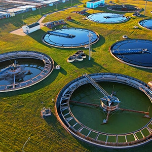
    Regenerative blowers, also known as side channel blowers or ring blowers, play a crucial role in wastewater treatment plants. They provide the necessary airflow for various processes, ensuring the efficient treatment of wastewater. This article explores the applications and benefits of regenerative blowers in wastewater treatment plants.

    Key Applications of Regenerative Blowers in Wastewater Treatment Plants

    1. Aeration Tanks

    Functionality: In aeration tanks, regenerative blowers supply air to promote the growth of aerobic bacteria, which are essential for breaking down organic matter in the wastewater.

    Applications:

    • Activated Sludge Process: Air is diffused through the wastewater to maintain adequate dissolved oxygen levels, supporting the biological treatment process.
    • Nitrification and Denitrification: Blowers help in maintaining aerobic conditions for nitrification and anoxic conditions for denitrification, crucial steps in nitrogen removal.
    1. Sludge Drying

    Functionality: Regenerative blowers are used to supply air for drying sludge, reducing its volume and weight, making it easier and more cost-effective to handle and dispose of.

    Applications:

    • Sludge Dewatering: Blowers provide airflow to drying beds or mechanical dryers, accelerating the evaporation of water from sludge.
    • Biosolids Treatment: Helps in reducing the moisture content of biosolids, transforming them into more stable and less odorous forms suitable for disposal or use as fertilizers.
    1. Odor Control

    Functionality: In wastewater treatment plants, regenerative blowers are used in odor control systems to capture and treat foul-smelling gases generated during the treatment process.

    Applications:

    • Ventilation: Blowers provide ventilation in areas where odorous gases are produced, such as sludge handling areas and anaerobic digesters.
    • Air Scrubbing: Blowers deliver air to scrubbers or biofilters, where odorous compounds are neutralized or removed.
    1. Pneumatic Conveying

    Functionality: Regenerative blowers are utilized in pneumatic conveying systems to transport dry, lightweight materials, such as powdered chemicals and dry sludge.

    Applications:

    • Chemical Handling: Blowers help in conveying powdered chemicals used in the treatment process, such as lime, activated carbon, and coagulants.
    • Sludge Transport: Used to pneumatically convey dry sludge to storage or disposal areas, reducing manual handling and improving efficiency.
    1. Filter Backwashing

    Functionality: In filtration systems, regenerative blowers provide the air required for backwashing filters, a process that cleans the filter media by reversing the flow of air and water.

    Applications:

    • Sand Filters: Blowers supply air for backwashing sand filters, removing trapped solids and restoring the filter’s efficiency.
    • Membrane Bioreactors (MBRs): Used in backwashing processes to clean membrane surfaces, maintaining high filtration performance and prolonging membrane life.

    Benefits of Using Regenerative Blowers in Wastewater Treatment Plants

    1. Energy Efficiency

    Functionality: Regenerative blowers are designed for efficient operation, consuming less energy compared to other types of blowers.

    Benefits:

    • Lower Operating Costs: Energy-efficient operation reduces electricity consumption, leading to lower operating costs.
    • Sustainable Operation: Efficient energy use contributes to the sustainability of wastewater treatment operations.
    1. Low Maintenance Requirements

    Functionality: Regenerative blowers have a simple design with few moving parts, resulting in minimal maintenance needs.

    Benefits:

    • Reduced Downtime: Low maintenance requirements mean less downtime, ensuring continuous operation of critical treatment processes.
    • Cost Savings: Lower maintenance costs due to fewer parts needing regular servicing or replacement.
    1. Quiet Operation

    Functionality: Regenerative blowers operate quietly, producing less noise compared to other types of blowers.

    Benefits:

    • Improved Work Environment: Quieter operation creates a more pleasant working environment for plant operators.
    • Compliance with Noise Regulations: Helps in meeting noise regulations and reducing noise pollution in the surrounding area.
    1. Reliable Performance

    Functionality: Regenerative blowers provide consistent airflow and pressure, ensuring reliable performance in various treatment processes.

    Benefits:

    • Process Stability: Reliable performance helps maintain stable treatment processes, enhancing the overall efficiency of the plant.
    • Durability: Robust construction ensures long-term reliability and durability, even in demanding operating conditions.
    1. Versatility

    Functionality: Regenerative blowers are versatile and can be used in various applications within the wastewater treatment plant.

    Benefits:

    • Multi-Functional: One type of blower can serve multiple functions, reducing the need for different equipment types.
    • Adaptability: Can be easily integrated into existing systems or used in new installations, offering flexibility in plant design and operation.

    Conclusion

    Regenerative blowers are indispensable in wastewater treatment plants, providing efficient and reliable airflow for aeration, sludge drying, odor control, pneumatic conveying, and filter backwashing. Their energy efficiency, low maintenance requirements, quiet operation, reliable performance, and versatility make them an ideal choice for enhancing the effectiveness and efficiency of wastewater treatment processes. By incorporating regenerative blowers, wastewater treatment plants can achieve better process control, reduce operating costs, and improve overall operational sustainability.

  • Utilizing System Protection Features in AC Drives

    Utilizing System Protection Features in AC Drives

    AC (Alternating Current) drives, also known as Variable Frequency Drives (VFDs), are essential components in modern industrial automation and control systems. They offer numerous advantages, including energy savings, improved process control, and extended equipment life. However, to fully leverage these benefits, it is crucial to understand and utilize the system protection features integrated into AC drives. These features safeguard the drive, motor, and associated equipment from various potential issues, ensuring reliable and efficient operation. This article explores the key system protection features in AC drives and how to effectively utilize them.

    1. Overcurrent Protection

    Functionality: Overcurrent protection safeguards the drive and motor from excessive current, which can cause overheating and damage. This feature detects abnormal current levels and shuts down the drive or limits the current to prevent harm.

    Utilization Tips:

    • Set Appropriate Limits: Configure the drive with the correct current limits based on the motor’s specifications and application requirements.
    • Monitor Regularly: Use the drive’s monitoring tools to keep an eye on current levels during operation. This helps in identifying trends that may indicate potential issues.
    • Routine Maintenance: Regularly inspect and maintain the motor and drive to ensure they operate within safe current limits.
    1. Overvoltage and Undervoltage Protection

    Functionality: These protections prevent damage caused by voltage levels outside the acceptable range. Overvoltage protection triggers when the supply voltage exceeds a safe threshold, while undervoltage protection activates when the voltage drops too low.

    Utilization Tips:

    • Voltage Range Setting: Ensure the drive’s voltage protection settings match the power supply characteristics and the motor’s voltage tolerance.
    • Power Quality Monitoring: Regularly monitor the quality of the power supply to detect and address issues like voltage sags, swells, and transients.
    • Use Surge Protectors: Install surge protection devices to safeguard against sudden voltage spikes that can cause overvoltage conditions.
    1. Overload Protection

    Functionality: Overload protection prevents the motor from operating beyond its rated capacity for an extended period, which can lead to overheating and premature failure. This feature detects overload conditions and reduces the drive’s output or shuts it down to protect the motor.

    Utilization Tips:

    • Proper Sizing: Ensure the motor and drive are appropriately sized for the application to avoid frequent overload conditions.
    • Configuration: Set the overload protection parameters based on the motor’s thermal characteristics and the application load profile.
    • Regular Checks: Periodically check the motor’s load and performance to ensure it operates within safe limits.
    1. Ground Fault Protection

    Functionality: Ground fault protection detects unintentional connections between the motor’s electrical components and the ground, which can cause dangerous current flow and potential damage.

    Utilization Tips:

    • Regular Inspections: Conduct routine inspections of the motor and drive wiring to identify and rectify any potential ground faults.
    • Isolation: Ensure proper insulation of all electrical components to prevent accidental grounding.
    • Set Sensitivity Levels: Configure the drive’s ground fault protection sensitivity according to the application’s requirements to detect even minor faults.
    1. Thermal Protection

    Functionality: Thermal protection monitors the temperature of the drive and motor, preventing overheating that can lead to failure. This feature typically includes sensors that trigger alarms or shut down the drive when temperatures exceed safe limits.

    Utilization Tips:

    • Sensor Placement: Ensure temperature sensors are correctly placed to accurately monitor critical areas of the motor and drive.
    • Cooling Systems: Maintain adequate cooling systems, such as fans or heat exchangers, to dissipate heat effectively.
    • Regular Cleaning: Keep the drive and motor free from dust and debris that can obstruct airflow and cause overheating.
    1. Short Circuit Protection

    Functionality: Short circuit protection detects and interrupts excessive current flow caused by short circuits, preventing damage to the drive and motor.

    Utilization Tips:

    • Circuit Breakers: Use appropriate circuit breakers and fuses to provide an additional layer of short circuit protection.
    • Regular Testing: Periodically test the drive’s short circuit protection functionality to ensure it responds correctly to faults.
    • Proper Wiring: Ensure all wiring and connections are correctly installed and maintained to minimize the risk of short circuits.

    Conclusion

    Utilizing system protection features in AC drives is vital for ensuring the longevity, reliability, and safety of both the drive and motor. By understanding and correctly configuring these features, operators can prevent damage from overcurrent, overvoltage, undervoltage, overload, ground faults, thermal issues, and short circuits. Regular monitoring, maintenance, and adherence to best practices are essential to fully leverage the protection capabilities of AC drives, leading to improved performance and reduced downtime in industrial applications. By incorporating these protective measures, industries can achieve more efficient and resilient operations, safeguarding their investments and enhancing productivity.

  • Advantages of HMIs

    Advantages of HMIs

    The human-machine interface (HMI) serves as a symbol of empowerment for operators. Through user-friendly interfaces, HMIs not only facilitate quicker decision-making but also drastically cut down on training periods, thus boosting operator efficiency. There are various ways HMIs improve operator efficiency:

    User-Friendly Interfaces for Quick Decision-Making
    HMIs transform the operator’s interaction by providing user-friendly interfaces designed to match human thought processes, enabling fast navigation and quick absorption of crucial data. With simplified menu layouts, contextualized data presentation, and easy-to-use controls, operators can promptly access essential information and make decisions with impressive speed and agility.

    Enhanced Operational Insights through Customizable Displays and Dynamic Data Presentation
    A fundamental aspect of HMI design involves its customizable dashboards and dynamic data visualization features. This functionality empowers operators to personalize displays according to their specific needs, ensuring instant access to vital metrics and operational parameters. Real-time data visualization further enhances this capability by delivering actionable insights at a glance, promoting informed decision-making and proactive responses to evolving production conditions. HMIs act as the forefront of operational transparency, providing comprehensive visibility into machine performance, production metrics, and process status. This increased transparency serves as a catalyst for proactive decision-making and heightened operational efficiency.

    In-Depth Understanding and Operational Metrics
    HMIs serve as portals to vast operational data, granting instant access to essential performance metrics such as production output, machine efficiency, energy usage, and quality measures. By organizing and displaying this data in a clear format, HMIs enable operators and management to gain a comprehensive view of operational intricacies, promoting well-informed decision-making and strategic planning.

    Dynamic Monitoring for Preventative Maintenance
    The hallmark of HMI excellence is its real-time monitoring capability, empowering operators to oversee machinery performance and process parameters. This immediate insight not only facilitates swift detection of anomalies or inefficiencies but also supports preventative maintenance efforts. By proactively addressing potential issues and mitigating unexpected downtime, HMIs play a crucial role in reinforcing operational continuity and maximizing asset utilization. In industrial automation, HMIs play a pivotal role in facilitating centralized control of complex systems. By integrating disparate elements into a unified operational structure, HMIs streamline operations and enhance resource efficiency, driving productivity forward.

    Unified Control and Operational Synergy
    HMIs function as the central hub of industrial operations, consolidating control features and data visualization into a single interface. This unified control framework not only promotes operational synergy but also enables operators to manage complex systems with accuracy and assurance. Through smooth integration with various equipment and machinery, HMIs foster operational flexibility and responsiveness, establishing a foundation for enhanced efficiency and resource utilization.

    When it comes to the advantages of HMIs, the transformative potential is limitless. From redefining data presentation to equipping operators with seamless control, HMIs lead the charge in operational efficiency and innovation. Their capacity to merge human insight with technological accuracy not only enhances productivity but also sets the stage for a future where industrial processes embody agility, resilience, and unwavering precision. As industries increasingly harness the vast capabilities of HMIs, it’s clear these interfaces are more than mere tools; they catalyze a new era of operational excellence, poised to redefine industrial automation in remarkable ways.

  • Why Use Flush Mounting Handles?

    Why Use Flush Mounting Handles?

    Flush mounting handles for circuit breakers are a practical and aesthetic innovation that can significantly enhance the functionality and safety of electrical systems. These handles, designed to sit flush with the panel surface, offer several benefits that make them an excellent choice for both residential and commercial applications. This article explores the various advantages of using flush mounting handles for circuit breakers.

    1. Improved Safety

    Functionality: Flush mounting handles are designed to be level with the surface of the panel, reducing the risk of accidental contact and improving overall safety.

    Benefits:

    • Reduced Tripping Hazards: With no protruding parts, flush mounting handles eliminate tripping hazards in areas with high foot traffic.
    • Enhanced Protection: These handles minimize the risk of accidental activation or deactivation of the circuit breaker, protecting both the equipment and personnel from unintended electrical disruptions.
    1. Space Efficiency

    Functionality: Flush mounting handles help save space in tight or crowded electrical enclosures, making them ideal for compact installations.

    Benefits:

    • Optimized Space Utilization: By not extending beyond the panel surface, flush mounting handles allow for more efficient use of space, accommodating additional components within the same enclosure.
    • Streamlined Design: The sleek, low-profile design contributes to a cleaner and more organized appearance, which is particularly beneficial in settings where space is at a premium.
    1. Enhanced Aesthetics

    Functionality: The flush design of these handles provides a modern, streamlined look that enhances the overall aesthetics of electrical panels and equipment.

    Benefits:

    • Professional Appearance: Flush mounting handles contribute to a polished and professional appearance, which is important in commercial and high-visibility environments.
    • Consistent Design: These handles blend seamlessly with the panel surface, maintaining a consistent and uniform look across the entire installation.
    1. Ease of Operation

    Functionality: Flush mounting handles are ergonomically designed for easy operation, providing a comfortable grip and smooth action.

    Benefits:

    • User-Friendly: The ergonomic design ensures that users can easily operate the circuit breaker, even in emergency situations.
    • Intuitive Use: The handles are designed to be intuitive, making it simple for users to understand and operate the breaker without extensive training.
    1. Durability and Reliability

    Functionality: Flush mounting handles are typically made from high-quality materials that offer durability and reliability, ensuring long-term performance.

    Benefits:

    • Robust Construction: Made from materials like stainless steel or reinforced plastics, these handles can withstand harsh environments and heavy use.
    • Long Service Life: The durable design reduces the need for frequent replacements, lowering maintenance costs and ensuring reliable operation over time.
    1. Customization Options

    Functionality: Flush mounting handles can be customized to meet specific application requirements, offering flexibility in design and functionality.

    Benefits:

    • Tailored Solutions: Customizable options allow for specific color coding, labeling, or even integration with other control elements, enhancing usability and functionality.
    • Application-Specific Designs: Custom designs can be created to fit unique installation requirements, ensuring optimal performance and compatibility with various circuit breaker types and sizes.

    Conclusion

    Flush mounting handles for circuit breakers offer numerous benefits, including improved safety, space efficiency, enhanced aesthetics, ease of operation, durability, and customization options. Their innovative design not only enhances the functionality of electrical systems but also contributes to a safer and more visually appealing installation.

    By incorporating flush mounting handles, electrical professionals can achieve a higher standard of safety and efficiency while maintaining a clean and modern appearance for their installations. Whether in residential, commercial, or industrial settings, the adoption of flush mounting handles represents a smart and forward-thinking approach to circuit breaker management.

  • How UPS Efficiency is Calculated

    How UPS Efficiency is Calculated

    Uninterruptible Power Supply (UPS) systems are vital for providing continuous power to critical equipment during outages and power disturbances. One of the key performance metrics for a UPS system is its efficiency, which indicates how effectively the UPS converts and delivers power. Understanding and calculating UPS efficiency is crucial for optimizing energy use, reducing operational costs, and ensuring environmental sustainability. This article explores how UPS efficiency is calculated and the factors that influence it.

    Understanding UPS Efficiency

    UPS efficiency refers to the ratio of the useful output power to the input power, expressed as a percentage. It measures how much of the input power is converted into usable output power, with the remainder lost as heat or other forms of energy. Higher efficiency means less energy is wasted, leading to lower operational costs and reduced environmental impact.

    UPS Efficiency Formula

    The basic formula for calculating UPS efficiency is: Efficiency (%) = (Output Power / Input Power) * 100

    Where:

    • Output Power: The amount of power delivered by the UPS to the connected load.
    • Input Power: The amount of power consumed by the UPS from the power source.

    Factors Influencing UPS Efficiency

    1. Load Level

    Functionality: The efficiency of a UPS can vary depending on the load level, which is the percentage of the UPS’s total capacity being utilized.

    Impact:

    • Optimal Load Range: UPS systems are typically most efficient within a specific load range, often between 40% to 80% of their rated capacity.
    • Efficiency Curve: The efficiency of a UPS generally increases with load up to a certain point, after which it may decline slightly.
    1. UPS Topology

    Functionality: Different UPS topologies (offline/standby, line-interactive, and online/double-conversion) have varying inherent efficiencies due to their design and operational characteristics.

    Impact:

    • Offline/Standby UPS: Generally has the highest efficiency (95% or higher) because it only engages the inverter during power disturbances.
    • Line-Interactive UPS: Slightly lower efficiency (90-95%) due to continuous voltage regulation.
    • Online/Double-Conversion UPS: Typically has the lowest efficiency (85-95%) because it continuously converts power, ensuring the highest level of protection and power quality.
    1. Environmental Conditions

    Functionality: The ambient temperature and ventilation in the environment where the UPS operates can affect its efficiency.

    Impact:

    • Heat Dissipation: Higher temperatures can reduce efficiency due to increased energy losses in cooling and heat dissipation.
    • Ventilation: Proper ventilation helps maintain optimal operating temperatures, enhancing efficiency.
    1. UPS Age and Maintenance

    Functionality: The age of the UPS and how well it is maintained can influence its efficiency.

    Impact:

    • Component Degradation: Over time, components such as capacitors and batteries degrade, reducing efficiency.
    • Regular Maintenance: Ensures that the UPS operates at peak efficiency by replacing worn components and performing necessary adjustments.

    Calculating UPS Efficiency in Practice

    1. Measure Input and Output Power

    Steps:

    • Input Power Measurement: Use a power meter to measure the total power consumed by the UPS from the power source.
    • Output Power Measurement: Measure the power delivered by the UPS to the connected load.

    Example:

    • Input Power: 1100 watts
    • Output Power: 1000 watts
    1. Apply the Efficiency Formula

    Calculation: Efficiency (%) = (1000W / 1100W) * 100 = 90.91%

    Real-World Considerations

    1. Efficiency at Different Load Levels

    Scenario: To determine how efficiency varies with load, measure the input and output power at different load levels (e.g., 25%, 50%, 75%, and 100% of UPS capacity).

    Observation: Plot these values to create an efficiency curve, helping identify the optimal operating range for maximum efficiency.

    1. Manufacturer Specifications

    Guidance: Manufacturers provide efficiency ratings under specific conditions. Compare these ratings with actual measurements to ensure the UPS operates as expected.

    1. Energy Efficiency Standards

    Context: Consider energy efficiency standards and certifications (e.g., ENERGY STAR) when selecting a UPS, as these standards provide benchmarks for high-efficiency performance.

    Conclusion

    Calculating UPS efficiency involves measuring the input and output power and applying a simple formula to determine the percentage of power effectively converted and delivered. Various factors, including load level, UPS topology, environmental conditions, and maintenance, influence UPS efficiency. Understanding these factors and regularly assessing UPS efficiency can help optimize energy use, reduce operational costs, and enhance the reliability of power protection systems.

    By focusing on efficient UPS operation, organizations can achieve significant energy savings, improve sustainability, and ensure the continuous, reliable operation of critical equipment.

  • Fuji’s X-Series RC-IGBT technology enhancements to the Dual.XT Module

    Fuji’s X-Series RC-IGBT technology enhancements to the Dual.XT Module

    Download the article | Watch Video Datasheet

    Fuji Electric’s new X-Series RC-IGBT technology enables a higher power rating in the Dual.XT IGBT module from ratings of 800A-1200V to 1000A-1200V & 600A-1700V to 800A-1700V in the existing module package. The technology makes it possible to replace the high-cost, large-form-factor PrimePACK™ modules in power electronic systems.

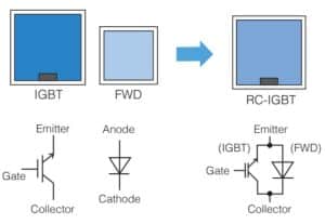
    Figure 1. The RC-IGBT chip schematic and equivalent circuit.
    Source:  Fuji Electric

    This article shows how the Fuji Dual.XT Module with RC-IGBT technology (see Figure 1) meets the most pressing needs of power semiconductors and includes a list of benefits and a summary of applications.

    Power Semiconductors: What’s Needed?

    Among the needs of power semiconductors, the miniaturization of power conversion systems is high on the list. Engineers are also seeking reduced costs and increased performance wherever possible. However, increasing the output power in a given package size leads to elevated temperatures, which is a risk factor for a shorter product lifetime.

    The Solution: Fuji Dual.XT Module with RC-IGBT Technology

    Fuji Electric’s RC-IGBTs integrate an IGBT and FWD on a single chip, using this technology and a 7th-generation X Series technology to create the line-up of the Dual.XT RC-IGBT modules with 1200V and 1700V ratings. Several critical aspects of this technology address the needs of modern power semiconductors.

    Higher Performance

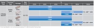
    Implementing Fuji Dual.XT module with the reverse conducting (RC) technology expands the previous Fuji V-Series and increases the present X-Series generation’s power rating in the Dual.XT package. Figure 2 shows how the Fuji Dual.XT Module fits Fuji’s current offerings and increases the power density and overall performance. 

    Figure 2. The Fuji Dual.XT Module with RC-IGBT technology takes its place in the X Series Dual.XT lineup. Source: Fuji Electric

    The 1000A-1200V Dual.XT module enables the replacement of 900A-1200V PrimePACK2, resulting in a more than 10% increase in module power rating.

    Miniaturization and Integration

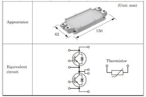
    By combining the IGBT and FWD on a single chip, the RC-IGBT technology reduces the number of chips and the total chip area, further contributing to equipment miniaturization and a smaller bill of materials (BOM). The X-Series RC-IGBT modules were developed to facilitate the downsizing of power electronic systems. Figure 3 shows the electric circuit and appearance along with the 62-mm x 150-mm dimensions.

    Figure 3. Appearance and equivalent circuit for the Dual.XT Modules.
    Source: Fuji Electronics

    Mitigation of Heat Generation

    The Dual.XT module with RC-IGBT technology achieves excellent heat dissipation using a high-performance ceramic insulating substrate made of aluminum nitride (AlN). In addition, by integrating the IGBT and FWD functions on one chip, the RC-IGBT has a larger heat dissipation area than either an IGBT or FWD alone (compared with conventional IGBT + FWD systems at the same rated current). 

    Not only are thermal resistance and heat dissipation greater, but it is now possible to have higher-rated currents for the same chip area. The wire bonding was optimized, along with the use of high-strength solder and high-heat-resistant silicone gel. Note that the maximum junction temperature Tvj, max is between 150°C and 175°C.

    Benefits of the Fuji Dual.XT Module with RC-IGBT Technology

    Using the Dual.XT Module with RC-IGBT technology has several benefits, including improved performance and efficiency, higher reliability, ease of use, miniaturization, and greater power density.

    Better Performance

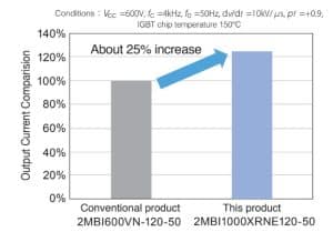
    The prior V-Series Dual.XT RC-IGBT module rating of 600A-1200V was increased to 1000A-1200V, leading to a higher rating in the same package. Figure 4 shows that the output current at the stated conditions has been increased by 25% compared with conventional products.

    Figure 4. Output current comparison during steady-state continuous operation.
    Source: Fuji Electronics

    Improved Efficiency

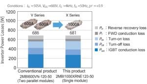
    As an example of improved efficiency, the RC-IGBT enhanced Dual.XT modules can replace two 600A modules in parallel with a single 1000A module in a 350kW inverter. This contributes to equipment miniaturization and reduces the number of gate drivers as well as the inverter loss.

    Figure 5. 350kW inverter loss comparison.
    Source: Fuji Electric 

    Higher Reliability

    The thermal capability designed into the Dual.XT RC-IGBT modules contributes to reliability and product life. The design considerations lead to a maximum junction temperature (Tvj, max) during operation from 150°C to 175°C, with more minor temperature fluctuations while ensuring high reliability.

    Ease of Use

    Because the Dual.XT module with RC-IGBT technology is available with solder pins and press-fit pins, it is easier to install and more flexible in its potential applications.

    Miniaturization

    The Dual.XT RC-IGBT modules offer a smaller footprint (9,300mm2 compared with 15,308mm2 for similar products) and a lighter weight (typically 250 grams compared with 850 grams). Thus, a higher power rating is achieved in a significantly smaller package.

    Greater Power Density

    The increased current and voltage ratings while maintaining the same or smaller package size means these chips have higher power density than similar products on the market. 

    Applications

    The Fuji Electric Dual.XT Module with RC-IGBT technology has numerous applications, including key markets like solar and wind power generation. The RC-IGBTs have been optimized for industrial applications, emphasizing upward compatibility with conventional IGBT and FWD chipsets. They are commonly used for everything from motor drives to uninterruptible power supplies.

    Conclusion

    For power engineers struggling to find a high-density power module solution that supports increased performance, miniaturization, reduced chip count, and mitigation of heat generation, look no further than the Fuji Dual.XT module with X-Series RC-IGBT technology. To learn more, contact Fuji Electric today.