Yes, you can use single-phase power with an AC drive, but there are some important considerations:
Single-Phase Input, Three-Phase Output Drives: Some AC drives are designed to accept a single-phase input and convert it to a three-phase output. This is useful when you have only single-phase power available but need to operate a three-phase motor.
Drive Rating: Ensure the drive is rated for single-phase input. Not all AC drives can accept single-phase power directly, so it’s important to check the manufacturer’s specifications.
De-Rating: When using a single-phase input, the drive often needs to be de-rated. This means that the drive can only handle a lower maximum current compared to its three-phase input rating. Manufacturers typically provide guidelines on how much to de-rate the drive.
Phase Conversion: If the drive is not designed for single-phase input, you can use a phase converter to generate a three-phase output from a single-phase input. However, this adds complexity and cost to the system.
Applications: Single-phase input drives are commonly used in residential or small commercial settings where three-phase power is not available. They are suitable for applications such as small machinery, fans, pumps, and other equipment requiring variable speed control.
Example of a Single-Phase Input AC Drive:
Input Voltage: 220-240V single-phase
Output Voltage: 220-240V three-phase
Power Rating: De-rated based on single-phase input (e.g., a drive rated for 3 HP with three-phase input might be de-rated to 1.5 HP with single-phase input)
Always consult the drive’s documentation and, if necessary, the manufacturer’s technical support to ensure proper selection and installation for your specific application.
Regenerative blowers, also known as side channel blowers, are robust and reliable machines widely used in various industrial applications. Regular maintenance of regenerative blowers is crucial to ensure their optimal performance, longevity, and efficiency. This article outlines essential tips and best practices for maintaining a regenerative blower.
Regular Inspection
Functionality: Conducting regular visual and operational inspections helps identify potential issues before they become serious problems.
Steps:
Visual Check: Inspect the blower for any signs of wear, damage, or leaks. Pay close attention to the housing, silencer area and impeller.
Operational Check: Listen for unusual noises and check for vibrations during operation. Unusual sounds or excessive vibrations can indicate misalignment or bearing issues.
Clean the Blower
Functionality: Keeping the blower clean prevents the buildup of dirt and debris, which can affect performance and cause damage.
Steps:
External Cleaning: Use a soft brush or cloth to remove dust and debris from the exterior surfaces of the blower.
Internal Cleaning: Internal cleaning of the unit is not required unless the inlet filter has been compromised.
Bearings
Functionality: Bearings ensures smooth operation and reduces friction, preventing wear and overheating.
Steps:
Check Manufacturer’s Guidelines: Refer to the blower’s manual for specific bearing type.
Sealed Bearings: The bearings used in Fuji blowers are sealed and should be replaced based on blower usage and temperature.
Monitor Operating Conditions
Functionality: Monitoring the blower’s operating conditions helps maintain optimal performance and detect potential issues early.
Steps:
Temperature Monitoring: Check the blower’s operating temperature regularly. Excessive heat can indicate problems such as overloading or inadequate ventilation.
Pressure Monitoring: Monitor the pressure levels to ensure they are within the specified range. Deviations from the norm can signal blockages or leaks in the system.
Inspect and Replace Filters
Functionality: Filters prevent contaminants from entering the blower, protecting internal components and ensuring clean air output.
Steps:
Regular Inspection: Inspect filters regularly for dirt and debris. Clogged filters can restrict airflow and reduce efficiency.
Replace as Needed: Replace filters according to the manufacturer’s recommendations or sooner if they appear dirty or damaged.
Check Electrical Connections
Functionality: Ensuring secure and proper electrical connections prevents issues such as power loss, short circuits, and electrical faults.
Steps:
Inspect Connections: Regularly inspect all electrical connections, including power supply, control circuits, and grounding.
Tighten Loose Connections: Tighten any loose connections to prevent arcing and ensure stable power supply.
Replace Worn or Damaged Parts
Functionality: Timely replacement of worn or damaged parts prevents further damage and maintains the blower’s performance.
Steps:
Identify Worn Parts: During inspections, identify any parts showing signs of wear or damage, such as bearings, seals, or impellers.
Replace Parts: Replace worn or damaged parts promptly with genuine replacements to ensure compatibility and performance.
Maintain Proper Ventilation
Functionality: Adequate ventilation prevents overheating and ensures that the blower operates within safe temperature limits.
Steps:
Check Ventilation: Ensure that the blower has sufficient airflow around it to dissipate heat.
Remove Obstructions: Clear any obstructions that may block airflow to and from the blower.
Follow Manufacturer’s Maintenance Schedule
Functionality: Adhering to the manufacturer’s maintenance schedule ensures that all necessary maintenance tasks are performed regularly and correctly.
Steps:
Refer to Manual: Consult the blower’s manual for the recommended maintenance schedule and procedures.
Schedule Maintenance: Set up a maintenance schedule based on the manufacturer’s guidelines and stick to it diligently.
Conclusion
Maintaining a regenerative blower involves regular inspection, cleaning, lubrication, monitoring, and timely replacement of parts. By following these essential tips and best practices, you can ensure the longevity, reliability, and optimal performance of your regenerative blower. Proper maintenance not only enhances efficiency but also reduces the risk of unexpected breakdowns and costly repairs, ensuring smooth and continuous operation in your industrial applications.
Choosing the right Uninterruptible Power Supply (UPS) is crucial for ensuring continuous operation during power outages and disturbances. One of the most critical factors in selecting a UPS is determining the appropriate battery runtime. This article explores how to calculate the necessary UPS battery runtime to meet your specific needs, ensuring that your essential equipment remains operational until power is restored or a generator comes online.
Understanding UPS Battery Runtime
UPS battery runtime refers to the duration for which a UPS can supply power to connected equipment during an outage. The runtime depends on the capacity of the UPS batteries and the power consumption of the connected devices. Accurately calculating the required runtime is essential for ensuring uninterrupted operation during power interruptions.
Steps to Determine UPS Battery Runtime
Identify Critical Loads
Functionality: Determine which equipment and devices need to be powered during an outage. Prioritize critical loads that require continuous power to prevent data loss, downtime, or other disruptions.
Steps:
List Equipment: Make a list of all devices that need UPS protection, such as servers, network equipment, workstations, and critical medical or industrial equipment.
Determine Power Requirements: Note the power consumption (in watts or VA) of each device. This information is typically found on the device’s nameplate or in the user manual.
Calculate Total Power Consumption
Functionality: Sum the power consumption of all critical loads to determine the total power requirement for the UPS.
Steps:
Add Power Consumption: Sum the wattage or VA ratings of all listed devices.
Example Calculation: If you have three devices with power consumption of 200W, 300W, and 500W, the total power requirement is 200W + 300W + 500W = 1000W.
Determine Desired Runtime
Functionality: Decide how long you need the UPS to power your equipment during an outage. This duration depends on several factors, including the typical duration of outages in your area and the time required to shut down systems safely or bring a generator online.
Considerations:
Short Outages: For brief outages (5-15 minutes), a shorter runtime may be sufficient to allow for an orderly shutdown.
Longer Outages: If you need to bridge the gap until a generator starts or power is restored, a longer runtime (30 minutes or more) may be necessary.
Check UPS Specifications
Functionality: Review the specifications of potential UPS systems to ensure they can provide the required runtime for your total power consumption.
Steps:
Manufacturer’s Runtime Charts: Refer to the manufacturer’s runtime charts or calculators, which show how long the UPS can power a given load.
Battery Capacity: Consider the battery capacity (measured in ampere-hours, Ah) and the UPS’s efficiency to determine if it meets your runtime needs.
Example Calculation
Scenario: You need to protect three servers, each consuming 300W, with a total power requirement of 900W. You want a runtime of 20 minutes to ensure enough time for a safe shutdown or generator startup.
Total Power Requirement: 900W.
Desired Runtime: 20 minutes (0.33 hours).
Using a manufacturer’s runtime chart, find a UPS that can support 900W for at least 20 minutes. If a UPS system’s runtime chart indicates it can provide 900W for 25 minutes, this UPS would meet your needs.
Factors Affecting UPS Battery Runtime
Battery Age and Condition
Impact: Battery performance degrades over time, reducing runtime. Regular maintenance and timely battery replacement are crucial for ensuring consistent performance.
Ambient Temperature
Impact: Batteries perform best at optimal temperatures (typically 20-25°C or 68-77°F). Higher temperatures can reduce battery life and runtime, while lower temperatures can impair battery performance.
UPS Efficiency
Impact: The efficiency of the UPS affects how much input power is converted into usable output power. Higher efficiency means less energy is wasted, providing a longer runtime for the same battery capacity.
Load Variations
Impact: Runtime decreases as the load increases. Ensure the UPS is not overloaded, as this can drastically reduce battery runtime and may cause the UPS to shut down prematurely.
Tips for Optimizing UPS Battery Runtime
Regular Maintenance: Perform regular maintenance checks and replace batteries as recommended by the manufacturer to ensure optimal performance.
Load Management: Prioritize and manage loads effectively to ensure critical equipment receives adequate power during outages.
Temperature Control: Maintain an optimal temperature for UPS batteries to maximize performance and lifespan.
Scalable Solutions: Consider scalable UPS systems that allow you to add battery modules for increased runtime as your needs grow.
Conclusion
Determining the appropriate UPS battery runtime is crucial for ensuring continuous operation during power outages. By identifying critical loads, calculating total power consumption, deciding on the desired runtime, and reviewing UPS specifications, you can select a UPS system that meets your needs. Regular maintenance, effective load management, and optimal environmental conditions will further ensure that your UPS system provides reliable backup power when you need it most.
Investing in the right UPS system with sufficient battery runtime is not only about protecting equipment but also about maintaining business continuity, safeguarding data, and ensuring operational efficiency during unexpected power interruptions.
Industrial circuit breakers are critical components in electrical systems, providing protection against faults such as overloads, short circuits, and electrical surges. Ensuring the safety and reliability of these breakers is paramount, as they safeguard both personnel and equipment in industrial environments. This article highlights the essential safety features that are needed for industrial circuit breakers.
Overload Protection
Functionality: Overload protection ensures that the circuit breaker trips when the electrical load exceeds the safe operating limits, preventing overheating and potential fires.
Key Features:
Thermal Trip Mechanism: Uses a bimetallic strip that bends when heated by excessive current, triggering the trip.
Adjustable Settings: Allows customization of the trip threshold to match specific operational requirements.
Short Circuit Protection
Functionality: Short circuit protection provides immediate interruption of electrical flow in the event of a short circuit, preventing damage to the electrical system and associated equipment.
Key Features:
Magnetic Trip Mechanism: Utilizes an electromagnet to trigger the trip when a high current surge is detected.
High Interrupting Capacity: Ensures the circuit breaker can safely interrupt large fault currents without damage.
Ground Fault Protection
Functionality: Ground fault protection detects unintentional paths to ground, which can cause electrical shock and equipment damage, and trips the breaker to interrupt the fault.
Key Features:
Residual Current Device (RCD): Monitors the difference between the live and neutral currents, tripping the breaker if an imbalance is detected.
Sensitive Detection: Capable of detecting low-level ground faults to ensure maximum safety.
Arc Fault Protection
Functionality: Arc fault protection identifies and mitigates the dangerous conditions caused by arcing faults, which can lead to electrical fires.
Key Features:
Arc Fault Circuit Interrupter (AFCI): Detects arcing conditions and trips the circuit breaker to prevent fires.
Advanced Sensing Technology: Uses pattern recognition to differentiate between harmless arcs (like those from a switch or motor) and dangerous ones.
Under Voltage Protection
Functionality: Under voltage protection ensures that the circuit breaker trips when the voltage drops below a predefined threshold, preventing damage to sensitive equipment.
Key Features
Voltage Sensing Mechanism: Continuously monitors voltage levels and trips the breaker if the voltage falls below a safe limit.
Adjustable Thresholds: Allows customization to accommodate different equipment requirements.
Overvoltage Protection
Functionality: Overvoltage protection trips the circuit breaker when the voltage exceeds a safe level, protecting equipment from damage caused by voltage spikes.
Key Features:
Surge Protection Devices (SPDs): Absorb and dissipate excess voltage, preventing it from reaching sensitive components.
Transient Voltage Suppression: Quickly responds to voltage spikes to protect connected equipment.
Remote Monitoring and Control
Functionality: Remote monitoring and control features allow operators to monitor the status of circuit breakers and control them from a central location, enhancing safety and operational efficiency.
Key Features
Digital Communication Interfaces: Enable integration with supervisory control and data acquisition (SCADA) systems.
Remote Trip and Reset Capabilities: Allow operators to trip or reset circuit breakers remotely, reducing the need for physical intervention.
Mechanical Interlocks
Functionality: Mechanical interlocks prevent simultaneous closing of breakers in certain configurations, ensuring safe operation and preventing equipment damage.
Key Features:
Key Interlocks: Ensure that certain operations can only be performed in a specific sequence, enhancing operational safety.
Locking Mechanisms: Physically prevent the breaker from closing if certain conditions are not met.
Dual Rating
Functionality: Dual rating allows circuit breakers to operate effectively under different conditions, ensuring safety across various operational scenarios.
Key Features:
AC and DC Ratings: Ensure the breaker can safely handle both alternating current (AC) and direct current (DC) applications.
Temperature Compensation: Adjusts the trip settings based on ambient temperature, ensuring consistent protection.
Diagnostic and Testing Features
Functionality: Diagnostic and testing features allow for regular inspection and testing of circuit breakers to ensure they function correctly and safely.
Key Features:
Self-Diagnostic Capabilities: Continuously monitor the health and performance of the breaker, alerting operators to potential issues.
Built-In Test Functions: Enable routine testing of the breaker’s functionality without removing it from service.
Conclusion
Industrial circuit breakers must incorporate a comprehensive array of safety features to ensure the protection of both personnel and equipment. Overload and short circuit protection, ground fault and arc fault detection, voltage protection, remote monitoring, mechanical interlocks, dual rating capabilities, and diagnostic features are all essential components that contribute to the safe and reliable operation of industrial electrical systems.
By integrating these safety features, industrial circuit breakers can effectively prevent electrical hazards, reduce the risk of equipment damage, and ensure compliance with safety standards, ultimately fostering a safer and more efficient working environment.
HMI touchscreens have become the primary control interface for car wash systems, supplanting older methods like push buttons and pilot lights. Today’s systems are significantly more advanced, with touchscreens being the standard interface as they are designed for user friendliness:
Users can effortlessly select wash types, customize options, and initiate or halt the washing process through touchscreen interaction
Offer real-time updates on the wash status, estimated completion time, and any issues requiring user attention
Connectable to remote monitoring systems
Facilitate centralized management and troubleshooting of car wash equipment
Moreover, they generate alerts for maintenance needs, such as component replacement or servicing, and record data on wash usage, customer preferences, and operational efficiency for analytics and business optimization. This data accumulation aids in enhancing business practices for car wash operators. These HMIs survive in carwash environments as they are tested and manufactured to meet shock, vibration, temperature, IP and NEMA environmental compliances.
Selecting the appropriate industrial pressure transmitter poses a significant challenge. When determining the ideal transmitter for your specific application, it’s crucial to ask the right questions during the decision-making process.
Question 1: What is the type of measurement?
Pressure measurement – The pressure transmitter’s most prevalent usage involves measuring both pressure and vacuum. In this application, the sensor experiences pressure, typically from sources like pumps or compressors
Level Measurement – The sensor gauges the variance in elevation between two locations. It can be employed for determining the height of a liquid column
Flow measurement – Differential pressure flow measurement relies on the pressure contrast within a moving fluid, facilitated by specialized primary components. These flow meters are instrumental in quantifying the flow of both liquids and gases within pipelines
Density measurement – Utilizing a differential pressure transmitter for density measurement proves to be an efficient approach for assessing the density of liquids
Question 2: What is the nature of the fluid? Considering the composition of the fluid, whether it’s gas, liquid, or vapor, holds significant importance in process measurement. Understanding the essential characteristics of the fluid is crucial for selecting the appropriate sensor for your industrial process.
Question 3: What type of pressure is being measured? The pressure type you intend to measure—Differential, Gauge, Absolute, or Vacuum—is a crucial factor in selecting the appropriate pressure transmitter.
Pressure transmitters designed for measuring pressure differentials and low pressures are highly suitable for tasks like monitoring filter clogging and determining fluid flow rates, especially when paired with depressurizing devices
Relative or vacuum sensors within pressure transmitters are better suited for gauging static pressure or negative gauge pressure, typically when the sensor is exposed to pressure from sources like pumps or compressors.
Absolute pressure transmitters are utilized in applications where pressure measurements are referenced relative to a perfect vacuum
Question 4: What is the fluid temperature? Fluid temperature is a critical aspect to contemplate when choosing a pressure transmitter. These transmitters are typically engineered to function effectively with liquids, gases, or steam within specific temperature thresholds. The minimum and maximum operational temperature parameters of pressure transmitters play a significant role in selecting a sensor for prolonged usage. In instances of elevated temperatures, employing pressure transmitters with diaphragm seals becomes imperative to safeguard the sensor electronics from the process measurements.
Question 5: What is my measurement range? The pressure range stands as the ultimate factor to ponder when deciding on a pressure transmitter. It’s imperative to select the zero and span parameters carefully to encompass the relevant range while avoiding surpassing the upper or lower limits necessary for accurate measurements.
Question 6: How corrosive is the fluid? The corrosive nature of the fluid, whether contaminated or chemically aggressive, must be carefully considered when choosing a pressure transmitter. Certain fluids can corrode sensitive materials under specific conditions, influencing the selection of materials for components in contact with the fluid. This selection significantly impacts the sensor’s lifespan. It’s essential to verify the compatibility of the fluid with the construction materials of your pressure transmitter.
Question 7: What process connections are planned? The variety of process connections—whether flanged, threaded, screwed, or hygienic—is another aspect to weigh when selecting the appropriate pressure transmitter. Different types of process connections cater to specific application needs:
Flanged connections enable high pressure ratings with minimal pressure drops
Threaded connections facilitate easy linking of hoses, tubes, and valves
Hygienic connections ensure food safety during processing through sanitary designs
Question 8: What are the environmental conditions? Environmental conditions within the application, including temperature, humidity, explosive atmosphere, dust, electromagnetic compatibility (EMC), vibrations, and safety integrity level (SIL), are additional crucial considerations when selecting a pressure transmitter. It’s essential to comprehend the operational context of the pressure transmitters and verify their ability to endure all potential conditions in their application environment. Furthermore, determining if your application necessitates specific safety certifications is imperative. Selecting a pressure transmitter with certifications such as SIL2 or ATEX, IECEx, etc., ensures compliance with safety requirements.
Question 9: What are the specific requirements of my application? Specific requirements tailored to the application:
When selecting a pressure transmitter, accuracy, stability, and response time emerge as pivotal considerations. Accuracy and stability hold paramount importance across all process measurement applications. Sensor accuracy denotes the degree to which the sensor output aligns with the actual measured value, influenced by various factors including temperature and static pressure.
Response time stands as a critical aspect in pressure transmitter selection. It signifies the duration for the transmitter to react to pressure changes, with swiftness being imperative. This responsiveness directly impacts decision-making speed, making it a vital indicator based on the transmitter’s information. Particularly for applications demanding instant information, considering response time is essential.
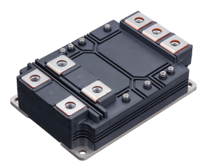
Fuji Electric Co., Ltd. (FE) is pleased to announce the launch of the HPnC Series, a new series of large-capacity industrial IGBT* modules for applications including power converters for solar and wind power generation systems. * Insulated-gate bipolar transistor
1. Background In order to achieve a decarbonized society, further expansion of the use of renewable energy sources such as solar and wind power is required, and reducing power generation costs has become an issue. IGBT modules are installed in power converters such as inverters and power conditioning systems (PCSs), and they play the role of changing frequencies and voltages by switching electricity on and off.
FE plans to release the HPnC Series large-capacity industrial IGBT* modules for applications including PCSs that perform power conversion in solar power generation systems and power converters for wind power generation systems. With increased rated current and voltage, these products improve the capacity and reduce the overall size of the power converters on which they are installed, thereby contributing to reducing power generation costs.
2. Features (1) Improves the capacity of power converters, contributing to reducing the number of units installed and expanding the installation area of solar panels
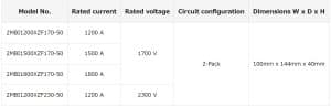
In addition to using the latest generation of IGBT chips, the module’s internal terminal layout and chip layout have been optimized and high heat dissipation materials have been applied to increase the current density per unit area, thereby achieving an industry-leading rated current of 1800 A (approximately 80% increase compared to the company’s previous products) while maintaining the size of the module. The number of power converters installed can be reduced by improving the capacity per unit. In solar power generation, they can also be used to expand the installation area of solar panels. These features contribute to improving power generation efficiency and reducing power generation costs.
(2) The 2300 V breakdown voltage product supports 1500 VDC, contributing to reducing the number of parts in power converters
Power converters are being upgraded to support higher voltage (1500 VDC) in order to improve power conversion efficiency and connection with large-scale power generation systems. The rated voltage required for an IGBT module installed on a 1500-VDC power converter is 2000 V or higher. To accommodate this, generally, two IGBT modules with a rated voltage of 1200 V or 1700 V are connected in series. FE has optimized the breakdown voltage structure of the IGBT chip and the FWD* chip and now offers a lineup of IGBT modules with a rated voltage of 2300 V.
One module can support a 1500-VDC power converter, which makes it possible to reduce the number of IGBT modules installed and other components such as wiring in peripheral circuits, allowing for a smaller power converter footprint. This contributes to lower power generation costs. * Free-wheeling diode
*The information contained in this release (product features, inquiry information, prices, etc.) is accurate as of the date of this announcement. This information is subject to change without prior notice.
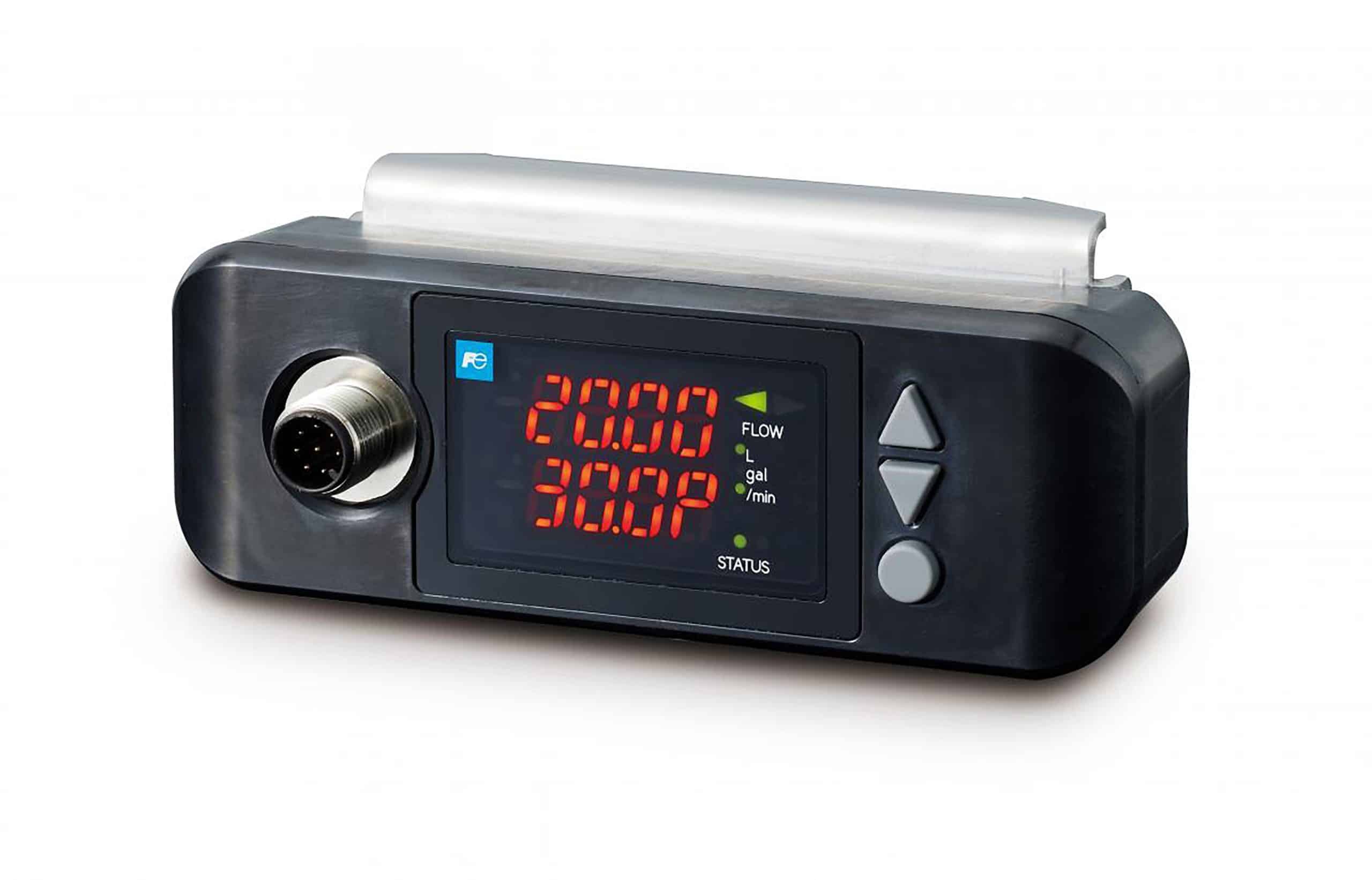
Edison, NJ –The new FSZ S-Flow is the latest integrated clamp-on ultrasonic flow meter for liquids in small pipes. Easy installation, space saving and easily deployable, the flow meter simultaneously displays volumetric flow and percentage, or temperature (option) at an affordable cost.
The FSZ S-Flow measures fluids in pipes from 1/4 inch to 1 ¼ inches and integrates the flow transmitter and detector, enabling it to eliminate the need for signal cable wiring while facilitating mounting to pipes by adopting a greaseless design. Benefits of the new S-Flow are process reliability, performance, and uptime, production labor and cost efficiency, operational agility for frequent and rapid changeovers and product safety, quality, and consistency.
The new FSZ S-Flow can be used in a wide variety of applications including pharma, biopharma, or life sciences, manufacturing, hot and cold-water piping for more efficient fan coil unit (FCU) operations and flow control in semiconductor manufacturing lines where small pipes or where pure water is used. In addition to piping for pure water manufacturing processes, cleaning processes, and equipment cooling, it can also be mounted inside equipment where there is densely-spaced small-diameter piping. Watch Video
Fuji Electric Corp. of America is a wholly owned subsidiary of Fuji Electric Co., Ltd., headquartered in Tokyo, Japan and has been responsible for sales and distribution of the company’s products since 1970. Fuji Electric Co., Ltd., celebrating their 100th anniversary this year, began developing power electronics equipment in 1923, and is a global leader in industrial products ranging from semiconductors, HMIs, contactors, relays, and power generation equipment to AC drives and uninterruptible power supply systems. For more information, please contact us or follow us on LinkedIn and Twitter.
Expanding the Lineup of the 7th-Generation X Series IGBT Modules
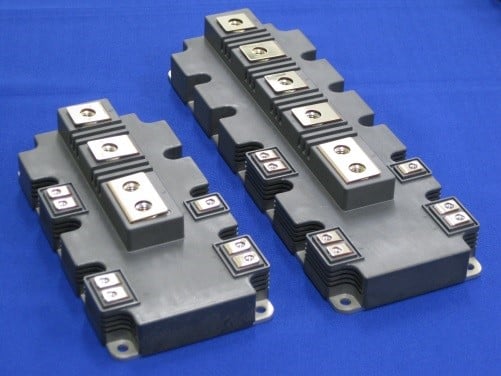
Fuji Electric Co., Ltd. (headquartered in Tokyo, Japan; led by President Michihiro Kitazawa) is pleased to announce that it has expanded the lineup of its 7th-generation X Series of IGBT*1 modules, targeting the large-scale wind power generation market, and has begun sample shipment of 1,700V withstanding voltage products. *1: Insulated Gate Bipolar Transistors
1. Aim IGBT modules are mounted on industrial equipment such as inverters for driving motors, uninterruptible power supplies (UPSs), and power conditioning systems (PCS) for wind or photovoltaic power generation facilities, and are key devices in achieving both energy conservation and a stable electric power supply.
In 2015, Fuji Electric launched its 7th-generation X Series of IGBT modules with withstanding voltages of 650V and 1,200V, contributing to energy conservation and a stable electric power supply for a wide range of equipment and facilities, including inverters for controlling air conditioners and motors, UPSs, and PCS. Fuji Electric has recently expanded its lineup of 1,700V withstanding voltage products, targeting the large-scale wind power generation market.
Amid increasing awareness of environmental issues, demand for clean energy, mainly from renewable energy sources, is growing around the world. The market for industrial-use IGBT modules is expected to grow at an annual rate of 3.5% from about 350 billion yen in 2018.*2 More and more large-scale wind power generation facilities are being constructed, particularly in Europe and China, and the global market for such facilities is expected to grow by 591 GW in 2018 and 8% annually by 2023 (source: GWEC). With this lineup expansion, Fuji Electric aims to further expand sales of its 7th-generation X Series of IGBT modules. *2: Fuji Electric’s original estimate from WSTS, etc.
7th-generation X Series, 1,700-V withstanding
2. Features of the 7th-Generation X Series 1) Achieves energy saving by reducing power loss The IGBT module combines and packages an IGBT, which turns the current on and off, with a diode, which has a freewheeling function (FWD).
With this product, Fuji Electric has made the IGBT and FWD thinner and the surface structure of the IGBT finer. This has reduced power loss during inverter operation by approximately 10% compared to the conventional product (6th-generation V Series). It also contributes to energy saving and to reducing the power cost of installed equipment.
2) Contributes to downsizing of equipment A newly developed insulating substrate has been applied to improve the heat dissipation of the module. In addition to the abovementioned reduced power loss, heat generation is suppressed, increasing the maximum guaranteed temperature for continuous operation from the conventional 150°C to 175°C, enabling an increase of up to 30%*3 in output current while maintaining the size of the installed equipment. This contributes to downsizing of equipment and reduction of total cost. *3: Value estimated from simulation results
3) Contributes to better equipment reliability The module structure and materials used were reviewed to improve stability and durability during operation at high temperatures. This contributes to improving the reliability of installed equipment.
3. Product Specifications
Rated voltage
Rated current
Package type
Sample shipment start date
1,700V
75A~400A
Std. 2in1
Starting from July 2019
225A~600A
Dual XT
650A~1,800A
PrimePACKTM
1,000A, 1,200A
HPnC
PrimePACKTM is a registered trademark of Infineon Technologies AG.
PrimePACKTM is a registered trademark of Infineon Technologies AG. *Information conveyed in this release (product features, inquiry information, etc.) is accurate as of the date of this announcement and is subject to change without prior notice.
Edison, NJ – Fuji Electric Corp is excited to announce the launch of the NEW MONITOUCH V10 HMI Series. The V10 joins the MONITOUCH V9, TechnoShot, and X1 series of HMI products available from Fuji Electric Corp. The new MONITOUCH V10 Series offers the high-speed processing of a quad-core CPU, allowing for stable operation and communication on high-load screens, an advanced storage device (eMMC) reducing startup/transfer time and man-hours, and the panel cutout size and functions are fully compatible with existing V series!
The new MONITOUCH V10 focuses on the six basic performance aspects of HMIs: Rendering and Operation, offering the highest screen switching speed and quickest input response time. Start-up and Transfer speed for the shortest power on time and highest screen data transfer speed. Communication speed reduces the read and write time of device data. Custom Code at the highest processing speed for rapid macro command execution. These features benefit designers, operators, and maintenance engineers in every application.
Fuji Electric Corp. of America is a wholly owned subsidiary of Fuji Electric Co., Ltd., headquartered in Tokyo, Japan and has been responsible for sales and distribution of the company’s products since 1970. Fuji Electric Co., Ltd. began developing power electronics equipment in 1923, and is a global leader in industrial products ranging from semiconductors, HMIs, contactors, relays, and power generation equipment to AC drives and uninterruptible power supply systems. For more information, please visit https://americas.fujielectric.com/or follow us on LinkedIn and Twitter.