
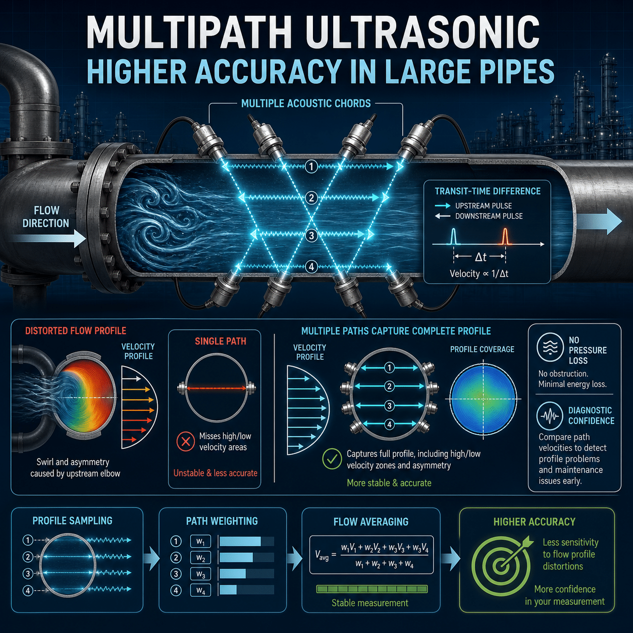
Measuring flow in a large pipeline is rarely as simple as installing a meter and reading the result. Pipe diameter, installation geometry, changing flow rates, upstream disturbances, fluid properties, and maintenance constraints can all affect measurement quality.
These challenges become especially important when small errors carry large financial or operational consequences. A one-percent error may sound minor, but in a pipeline moving thousands of units per hour, it can represent a substantial discrepancy over time.
Multipath ultrasonic flowmeters address this problem by measuring velocity across several acoustic paths instead of relying on a single point or line. The additional paths allow the meter to capture more of the actual flow profile, recognize distortion, and produce a more representative estimate of average velocity.
How Transit-Time Ultrasonic Measurement Works
Many ultrasonic meters used in large liquid and gas pipelines operate on the transit-time principle.
Transducers send ultrasonic pulses both downstream and upstream through the flowing fluid. The pulse traveling with the flow arrives slightly sooner than the pulse traveling against it. The meter uses this difference in transit time to calculate fluid velocity along the acoustic path.
The basic sequence is:
- An ultrasonic pulse travels diagonally across the pipe in the downstream direction.
- Another pulse travels along the same path in the upstream direction.
- The meter measures the difference between the two travel times.
- The electronics calculate path velocity.
- Path velocity is converted into average pipe velocity.
- Average velocity is multiplied by the pipe’s internal cross-sectional area to determine volumetric flow.
The time difference can be extremely small, so accurate measurement depends on precise timing, stable signal detection, correct pipe dimensions, and a reliable understanding of the velocity distribution inside the pipe.
Why One Acoustic Path May Not Be Enough
Flow velocity is not uniform across a pipeline.
Under ideal conditions, the velocity profile may be reasonably symmetrical, with slower fluid near the pipe wall and faster fluid toward the center. Real installations, however, often produce profiles that are skewed, flattened, swirling, or otherwise distorted.
Common causes include:
- Elbows
- Tees
- Partially open valves
- Reducers and expanders
- Pumps and compressors
- Flow conditioners
- Headers and manifolds
- Changes in operating rate
- Deposits or internal roughness
- Insufficient straight pipe
A single acoustic path samples only one portion of this profile. If that portion is moving faster or slower than the true cross-sectional average, the calculated flow may be biased.
The problem is similar to estimating the average traffic speed on a multi-lane highway by observing only one lane. The result may be correct if all lanes behave similarly, but it becomes unreliable when one lane moves differently from the others.
What Makes a Flowmeter “Multipath”?
A multipath ultrasonic flowmeter uses several pairs of transducers to create multiple acoustic paths through the pipe. These paths may cross the pipeline at different heights, angles, or orientations.
Each path produces an independent velocity measurement. The meter then combines the measurements using a mathematical weighting method designed to estimate the average velocity across the entire pipe.
Depending on the application and meter design, the instrument may use:
- Paths placed at different distances from the pipe center
- Crossed paths that help detect asymmetry
- Paths in more than one measurement plane
- Reflective paths that make multiple traverses through the fluid
- Redundant paths for diagnostics and continued operation
The number of paths alone does not determine performance. Path placement, transducer quality, signal processing, calibration, meter-body geometry, and the integration algorithm are equally important.
More Complete Sampling of the Velocity Profile
The primary advantage of a multipath meter is broader sampling.
A path near the center of the pipe may encounter higher velocity, while paths closer to the walls measure slower regions. By combining strategically located measurements, the flow computer can estimate the cross-sectional average more accurately than a single path usually can.
Multipath sampling is especially valuable in large pipelines because the distance between the centerline and the pipe wall is substantial. A local velocity measurement may not represent the full flow field.
Well-designed path geometry reduces the meter’s sensitivity to reasonable changes in the velocity profile. As the process rate or upstream conditions change, the meter can continue to form a representative average rather than depending on one fixed sample region.
Better Handling of Asymmetric Flow
An upstream elbow can push the highest-velocity region away from the pipe center. Two elbows in different planes can create an even more complicated profile with swirl and cross-flow components.
A single-path meter may interpret this local shift as a change in total flow. A multipath meter can compare velocities from different parts of the pipe and compensate more effectively for the asymmetry.
For example, if the paths on one side consistently report higher velocity than paths on the opposite side, the meter can identify that the flow profile is not symmetrical. Its integration algorithm uses the combined path data to reduce the bias that any one path might introduce.
This does not mean multipath technology eliminates installation requirements. Severe distortion can still affect accuracy. It does, however, provide greater tolerance and more information about what is happening inside the pipe.
Improved Detection of Swirl
Swirl occurs when fluid rotates around the pipeline axis while continuing to move downstream. It may result from elbows, valves, pumps, compressors, or complex piping configurations.
Swirl can influence an ultrasonic path differently depending on its orientation. In a crossed-path arrangement, one path may be affected in one direction while another responds differently.
Comparing those paths helps the meter distinguish axial flow from rotational components. Designs using multiple measurement planes can be particularly effective at identifying complex flow patterns.
The ability to detect swirl is valuable for two reasons:
- It helps the meter maintain accuracy within its design limits.
- It provides a diagnostic indication that the installation or flow condition may be less than ideal.
Reduced Sensitivity to Individual Path Errors
A single-path instrument depends entirely on one acoustic measurement. If that path is affected by deposits, gas bubbles, liquid droplets, weak signal strength, transducer degradation, or electronic noise, the meter’s only velocity measurement may become unreliable.
A multipath meter provides more measurement information. Its diagnostics may compare paths and identify one that behaves differently from the rest.
Depending on the design and configuration, the instrument may:
- Flag the affected path
- Exclude invalid data
- Continue operating in a degraded mode
- Estimate flow using the remaining valid paths
- Generate a maintenance alert before total measurement is lost
Redundancy does not make the meter immune to common-mode problems. If every path is affected by the same fluid condition or incorrect pipe-area value, the reported flow can still be wrong. Nevertheless, path-to-path comparison is a powerful diagnostic tool.
Lower Pressure Loss
Ultrasonic meters generally have no primary element projecting into the flow stream. A full-bore meter can provide an essentially unobstructed flow passage.
Compared with technologies that create a differential pressure, this can reduce permanent pressure loss and the associated pumping or compression energy.
The benefit is particularly significant in large pipelines, where even a small additional pressure drop may have a meaningful energy cost.
An unobstructed bore also makes ultrasonic meters attractive for applications involving:
- High flow rates
- Large pipe diameters
- Bidirectional flow
- Fluids carrying limited solids
- Processes that cannot tolerate a major restriction
- Systems where pressure loss must be minimized
Wide Measurement Range
Multipath ultrasonic meters can offer a broad usable flow range. Multiple paths provide stable sampling as the velocity profile changes between low and high rates.
At low velocity, however, the upstream and downstream transit times become very similar. Accurate timing and signal processing are therefore critical. At high velocity, turbulence, acoustic refraction, and signal attenuation may become more influential.
Actual turndown depends on the meter, fluid, pipeline geometry, required uncertainty, and operating conditions. A wide published range should not be treated as guaranteed performance for every installation.
Path Diagnostics Reveal More Than a Flow Value
One of the strongest advantages of multipath measurement is the amount of diagnostic information it can provide.
Depending on the meter, available indicators may include:
- Velocity on each path
- Speed of sound on each path
- Path-to-path velocity agreement
- Path-to-path speed-of-sound agreement
- Signal strength
- Gain or amplification level
- Signal-to-noise ratio
- Transit-time quality
- Rejected pulse count
- Turbulence indicators
- Profile symmetry
- Swirl indicators
- Active or failed paths
These values help distinguish a genuine process change from a measurement problem.
If the total flow changes while all paths remain consistent, the change is more likely to be real. If one path suddenly deviates while the others remain stable, the issue may involve that path’s transducers, cabling, electronics, or acoustic conditions.
Speed of Sound as a Diagnostic Tool
The meter calculates the fluid’s speed of sound as part of the transit-time measurement. Under uniform fluid conditions, different paths should generally report similar values.
A disagreement among paths may indicate:
- Temperature stratification
- Composition differences
- Liquid accumulation in a gas line
- Entrained gas in a liquid
- Contamination
- Deposits affecting a path
- Incorrect signal detection
- Transducer or electronics problems
In some applications, measured speed of sound can also be compared with an expected value based on fluid composition, pressure, and temperature. A significant mismatch may reveal incorrect process data or an unexpected change in the fluid.
Accuracy Still Depends on Pipe Area
An ultrasonic meter determines velocity, but volumetric flow also depends on the pipe’s internal cross-sectional area.
An incorrect internal diameter creates a direct bias in the flow calculation. Potential sources of error include:
- Incorrect pipe schedule
- Manufacturing tolerances
- Internal coating thickness
- Corrosion
- Scale or wax buildup
- Liners
- Deformation
- Incorrect temperature or pressure compensation
For high-accuracy service, the effective internal diameter must be established carefully. In metering runs, the bore may be precisely measured and matched to adjacent piping.
Multipath measurement cannot compensate for an incorrect area value shared by the entire calculation.
Installation Geometry Still Matters
Multipath meters tolerate disturbed flow better than simpler measurement arrangements, but they do not make installation effects disappear.
Accuracy can still be influenced by:
- Distance from elbows and valves
- Orientation relative to upstream disturbances
- Meter-body alignment
- Gasket intrusion
- Internal diameter steps
- Protruding welds
- Surface roughness
- Flow-conditioner placement
- Pipe contamination
- Temperature stratification
The manufacturer’s installation requirements should therefore be followed, including recommendations for straight runs and transducer-plane orientation.
Where space is limited or uncertainty requirements are demanding, computational analysis, laboratory testing, or calibration with the actual piping configuration may be justified.
Clamp-On Versus Inline Multipath Meters
Multipath technology can be applied in both inline and clamp-on designs, but their uncertainty sources differ.
Inline meters
Inline meters integrate the acoustic paths into a manufactured meter body. Their transducer positions, acoustic geometry, and internal diameter can be tightly controlled.
They are generally favored for demanding applications such as custody transfer, allocation, and high-value process measurement.
Clamp-on meters
Clamp-on transducers are mounted on the outside of an existing pipe. They avoid cutting into the pipeline and can be installed without interrupting service.
Their performance depends heavily on accurate knowledge of:
- Pipe outside diameter
- Wall thickness
- Pipe material
- Liner or coating
- Fluid properties
- Transducer spacing
- Acoustic coupling
- Pipe condition
Multipath clamp-on arrangements can improve profile coverage and diagnostic confidence, but external installation introduces additional variables that must be controlled carefully.
Calibration and Verification
A multipath meter may be mathematically sophisticated, but calibration remains essential when low uncertainty is required.
Flow calibration compares the complete meter against a traceable reference under controlled conditions. For some applications, the meter may be calibrated at multiple flow rates to establish its performance curve.
Important considerations include:
- Calibration fluid
- Pressure and temperature
- Reynolds-number range
- Upstream piping configuration
- Flow conditioner
- Meter orientation
- Bidirectional operation
- Electronic configuration
After installation, verification should include more than checking the displayed flow value. Baseline diagnostic data should be recorded so later changes can be recognized.
A useful baseline may include path velocities, speed of sound, signal strength, gain, profile indicators, and zero-flow behavior.
Common Misconceptions
“More paths automatically mean better accuracy.”
Additional paths can improve sampling, but performance also depends on where the paths are positioned, how they are weighted, and how well the meter is calibrated. A well-designed four-path meter may outperform a poorly designed meter with more paths.
“Multipath meters do not need straight pipe.”
They may be less sensitive to profile distortion, but upstream geometry still affects the flow field. Installation requirements remain important.
“If all paths are working, the measurement must be correct.”
All paths can agree while the flow result remains biased by an incorrect internal diameter, configuration error, calibration problem, or common fluid effect.
“Ultrasonic meters are maintenance-free.”
They have no moving parts in the flow stream, but they still require diagnostic review, electronics checks, transducer evaluation, and inspection for deposits or process changes.
“Diagnostics can replace calibration.”
Diagnostics help determine whether the meter is behaving consistently. They do not independently establish traceable measurement accuracy.
A Practical Commissioning Checklist
Before placing a multipath ultrasonic meter into service:
- Verify the meter size, bore, pressure class, and flow direction.
- Confirm that the installed meter matches the configured serial number and calibration data.
- Review upstream and downstream piping against installation requirements.
- Inspect for gasket, weld, or diameter intrusions.
- Verify pressure, temperature, composition, and density inputs where required.
- Confirm units, scaling, communications, and low-flow cutoff settings.
- Compare path velocities and speed-of-sound readings.
- Check signal strength, gain, and signal-to-noise indicators.
- Evaluate zero-flow behavior where a true zero condition can be established.
- Record a diagnostic baseline under stable operating conditions.
- Confirm that alarms for path failure and degraded operation are enabled.
- Document the normal diagnostic ranges for future comparison.
The Bottom Line
Multipath ultrasonic flowmeters improve measurement accuracy by observing more of the flow field.
Instead of relying on one acoustic path to represent an entire large pipeline, they measure velocity across several regions and combine the results into a more representative average. This reduces sensitivity to asymmetric profiles, provides better insight into swirl, and creates valuable diagnostic redundancy.
Their advantages are substantial: no significant flow obstruction, low pressure loss, broad operating range, and detailed information about measurement health.Multipath technology, however, is not a substitute for proper meter selection, accurate pipe dimensions, sound installation, calibration, and ongoing verification. Its greatest value comes from combining better physical sampling with intelligent diagnostics, and using both to understand not just the reported flow, but the quality of the measurement behind it