
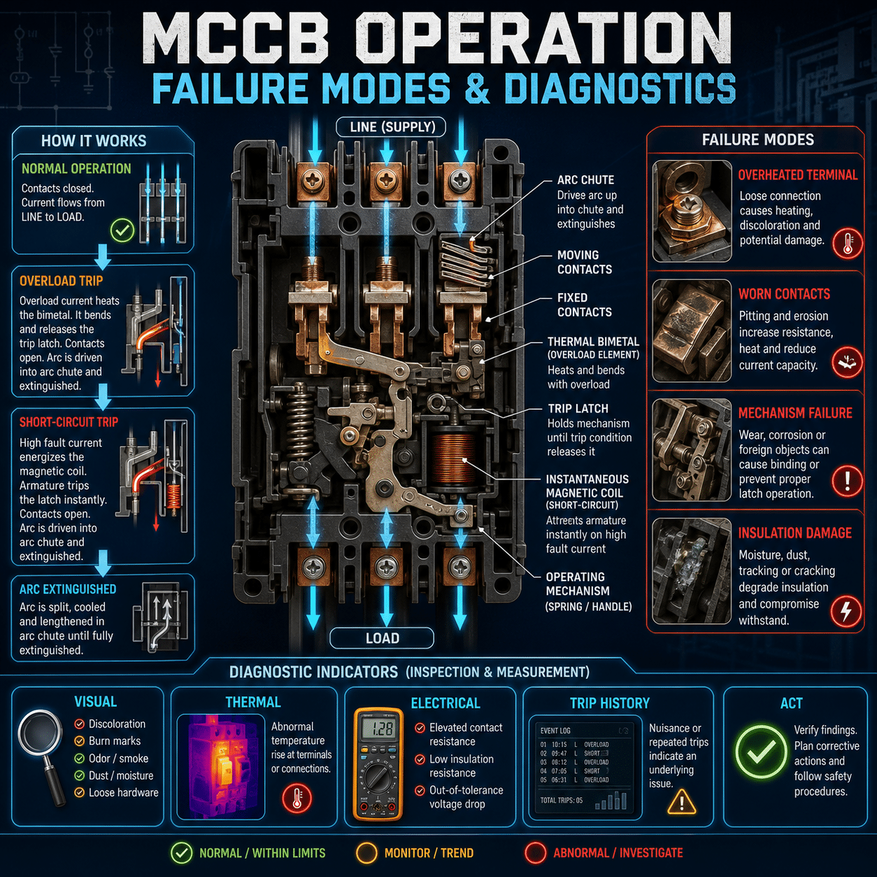
Molded-case circuit breakers are often treated as simple on-off devices. Under normal conditions, they carry current. During an overload or short circuit, they trip. When a breaker begins opening unexpectedly, or fails to open when it should, the investigation can quickly become more complicated.
An MCCB is both a mechanical switching device and a protective device. Its performance depends on contacts, springs, latches, conductors, terminals, sensors, and the trip unit working together. Understanding those parts makes it easier to distinguish a genuine electrical fault from a damaged breaker, poor connection, incorrect setting, or application problem.
What Is an MCCB?
A molded-case circuit breaker, or MCCB, protects electrical conductors and equipment against excessive current. Its components are enclosed in an insulating molded housing, and many MCCBs also provide a means of manually isolating a circuit.
Compared with miniature circuit breakers, MCCBs typically support higher current ratings, greater interrupting capacities, and more adjustable protection options. They are widely used in industrial switchboards, distribution panels, motor-control systems, generators, HVAC equipment, and commercial facilities.
Depending on its design, an MCCB may protect against:
- Long-duration overloads
- Short circuits
- Ground faults
- Phase imbalance or phase loss
- Other abnormal conditions detected by an electronic trip unit
Not every breaker provides every protective function. The installed trip unit and its settings determine what the device can detect.
How an MCCB Interrupts Current
When an MCCB detects a fault, its trip mechanism releases a stored-energy operating mechanism. The contacts separate rapidly, even if an operator holds the handle in the ON position. This “trip-free” behavior prevents the breaker from being forced closed during a fault.
Opening contacts create an electrical arc. The breaker directs that arc into an arc chute, where metal plates divide, cool, and lengthen it until the current is interrupted.
The breaker must contain the thermal and mechanical energy produced during this event. Its interrupting rating therefore matters just as much as its continuous-current rating. A breaker applied where the available fault current exceeds its rating may fail catastrophically instead of safely clearing the fault.
Thermal-Magnetic and Electronic Trip Units
MCCBs generally use either thermal-magnetic or electronic trip technology.
Thermal overload protection
A thermal element responds to sustained overcurrent. Current heats a bimetallic component, causing it to bend until the trip mechanism releases.
The response is intentionally time-dependent. A moderate overload may take seconds or minutes to trip the breaker, while a heavier overload produces a faster response. Ambient temperature, enclosure temperature, loading history, and airflow can influence thermal behavior.
Magnetic short-circuit protection
A magnetic element responds quickly to high fault current. When current exceeds its pickup level, electromagnetic force operates the trip mechanism with little intentional delay.
This function protects the circuit against severe short circuits rather than ordinary operating overloads.
Electronic protection
An electronic trip unit uses current sensors and digital or analog electronics to evaluate current. Depending on the model, it may provide adjustable:
- Long-time pickup and delay
- Short-time pickup and delay
- Instantaneous pickup
- Ground-fault pickup and delay
Advanced trip units may also record event data, identify the cause of a trip, measure electrical quantities, and communicate with a monitoring system.
What the Handle Position Means
Many MCCBs have three handle positions:
- ON: The contacts are commanded closed.
- OFF: The breaker has been opened manually.
- TRIPPED: The protective or trip mechanism has operated.
The tripped position is normally between ON and OFF. To reset the breaker, the handle must usually be moved fully to OFF before it can be moved back to ON.
A breaker that will not reset may still be receiving a trip command, may have an attached interlock or undervoltage device preventing closure, or may have internal mechanical damage. Repeatedly forcing the handle is not a valid diagnostic method.
Common MCCB Failure Modes
Loose or high-resistance connections
Loose terminals, poor crimps, damaged conductors, contamination, and incorrect hardware can create resistance at a connection. The resulting heat may discolor insulation, oxidize metal, weaken spring pressure, and damage the breaker body.
Because heating is proportional to the square of current multiplied by resistance, even a modest increase in connection resistance can become serious under heavy load.
Typical indicators include:
- One terminal hotter than comparable phases
- Discolored or melted insulation
- Burned odor
- Oxidation around the lug
- Deformed breaker housing
- Abnormal voltage drop across the connection
A hot terminal does not automatically prove that the breaker itself is defective. The conductor preparation, lug, torque, loading, and installation method all require inspection.
Contact erosion and overheating
Every interruption produces some contact wear. High fault currents, frequent switching, contact bounce, and improper application can accelerate erosion.
Damaged contacts may develop increased resistance, leading to additional heating during normal operation. Internal contact condition is not always visible without disassembly, and many MCCBs are not intended to be field-serviced internally.
Possible indicators include:
- Abnormal temperature rise through the breaker
- Excessive voltage drop across a closed pole
- Crackling or arcing sounds
- Burning odor
- Visible smoke or case damage
- Uneven phase temperatures under balanced loading
Nuisance or unexplained tripping
An unexpected trip is not necessarily a nuisance trip. The breaker may be correctly responding to a condition that has not yet been identified.
Possible causes include:
- Sustained overload
- Motor starting current
- Transformer inrush
- Capacitor energization
- Harmonic current
- High ambient temperature
- Incorrect trip settings
- Ground leakage
- Intermittent short circuit
- Loose connection
- Failing load equipment
- Poor coordination with downstream protection
The trip curve and actual current profile must be compared. Looking only at steady-state current can miss brief starting or inrush events.
Failure to trip
A breaker that fails to operate during a fault presents a severe safety risk. Causes may include a seized mechanism, damaged trip unit, incorrect settings, contamination, corrosion, improper maintenance, misapplication, or internal damage from a previous interruption.
This condition may not be visible during normal operation. Periodic inspection and testing are therefore critical where reliability requirements or applicable standards demand them.
Failure to close or remain closed
An MCCB may refuse to close because:
- It has not been fully reset
- A fault remains on the circuit
- An undervoltage release is not energized
- A shunt-trip signal remains active
- A mechanical interlock is engaged
- The operating mechanism is damaged
- An accessory is incorrectly installed or wired
If the breaker trips immediately after closing, the circuit should be treated as faulted until testing establishes otherwise.
Insulation deterioration
Heat, moisture, contamination, conductive dust, chemicals, age, and electrical stress can weaken insulation. Carbonized tracking paths may eventually support surface current or arcing.
Warning signs include:
- Cracks in the molded case
- Carbon deposits
- Surface tracking
- Moisture or contamination
- Evidence of flashover
- Reduced insulation resistance
- Ground-fault operation
A cracked, carbonized, or arc-damaged case generally calls for replacement rather than cosmetic cleaning.
Internal mechanical wear
Springs, pivots, latches, and linkages can wear, corrode, or seize. Breakers that operate infrequently may still develop problems because of contamination or hardened lubrication.
Indicators may include:
- A handle that feels unusually loose or stiff
- Incomplete movement
- Failure to latch
- Delayed or inconsistent operation
- A pole that does not open or close with the others
Mechanical concerns should be evaluated using manufacturer-approved procedures. Operating a suspect breaker repeatedly can make the condition worse.
Diagnostic Indicators That Matter
Trip-unit information
Electronic trip units may display LEDs, fault codes, target indicators, current values, or stored event records. This information should be captured before control power is removed or the breaker is reset, because resetting may clear useful evidence.
Important data can include:
- Trip type
- Fault magnitude
- Affected phase
- Time and date
- Ground-fault level
- Pre-trip current
- Breaker operation count
Temperature patterns
Thermal imaging can identify abnormal heating while equipment is energized and under meaningful load. The pattern matters more than temperature alone.
Useful comparisons include:
- Incoming versus outgoing terminals
- One phase versus the other phases
- The breaker versus adjacent breakers carrying similar loads
- Current temperature versus earlier inspection records
Temperature must be interpreted in context. Load current, ambient temperature, emissivity, enclosure conditions, airflow, and phase imbalance all affect the reading.
Voltage drop
Measuring voltage drop across each closed pole can reveal high-resistance paths. Comparing poles under similar current is often more useful than considering one measurement in isolation.
Because this test involves energized equipment, it should only be conducted under an appropriate electrical-safety program by qualified personnel using properly rated instruments and protective equipment.
Sound, smell, and appearance
Crackling, buzzing, burning odor, discoloration, soot, blistering, and deformation are significant warning signs. Equipment displaying evidence of active arcing, severe overheating, or case damage should not be repeatedly operated for troubleshooting.
Visual inspection should also check for:
- Loose or missing hardware
- Incorrect conductor size
- Improperly seated accessories
- Contamination
- Corrosion
- Damaged barriers
- Blocked ventilation
- Evidence of water entry
Current and event measurements
A clamp meter, power-quality analyzer, or monitoring system may reveal overloads, imbalance, harmonics, inrush, or intermittent faults. Measurements should capture the operating cycle, not just a single moment after the system has stabilized.
Maintenance and operating history
A breaker’s history can explain conditions that a visual inspection cannot. Useful records include:
- Previous fault interruptions
- Trip events
- Maintenance dates
- Test results
- Loading trends
- Environmental exposure
- Number of mechanical operations
- Changes to trip settings
- Recent equipment modifications
A breaker that has interrupted a major fault may require inspection, testing, or replacement even if it can be reset.
A Practical Troubleshooting Sequence
When an MCCB trips or behaves abnormally, a structured investigation is safer and more effective than immediately resetting it.
1. Preserve the evidence
Record handle position, trip indicators, alarm messages, temperatures, load conditions, and the operating event that preceded the trip. Retrieve electronic event data before resetting the device if possible.
2. Make the area safe
Follow the facility’s electrical-safety procedures. Inspect for smoke, odor, deformation, loose material, water, or signs of arcing. Do not close a visibly damaged breaker.
3. Identify the trip function
Determine whether the event was caused by long-time, short-time, instantaneous, or ground-fault protection. This greatly narrows the investigation.
4. Inspect the circuit and connected load
Look for damaged cables, failed motors, shorted components, ground faults, jammed machinery, overload conditions, and recent changes to the system.
5. Verify the application
Confirm the breaker rating, interrupting capacity, conductor size, trip-unit configuration, accessory wiring, and coordination requirements. Verify settings against the approved protection study or design documentation.
6. Measure and compare
Where it is safe and appropriate, compare phase currents, voltage drops, terminal temperatures, and insulation-test results. Look for patterns rather than relying on one isolated value.
7. Test the breaker appropriately
Testing may include mechanical operation, insulation resistance, contact resistance, primary-current injection, secondary injection, or trip-unit functional testing. The correct method depends on the breaker design and manufacturer’s instructions.
A push-to-trip button verifies only part of the mechanical trip path. It does not prove that the complete overcurrent-protection system will respond correctly to actual current.
8. Correct the root cause
Replacing a breaker will not solve an overloaded circuit, loose termination, damaged cable, incorrect setting, excessive enclosure temperature, or poorly coordinated protection scheme. Resolve the underlying condition before returning the system to service.
Resetting Is Not Troubleshooting
Repeatedly resetting an MCCB without identifying the cause can expose equipment and personnel to escalating risk. A downstream fault may worsen with each re-energization, and a breaker already damaged by fault current may not safely interrupt the next event.
Before reclosing, there should be a reasonable technical basis for believing that:
- The fault has been identified and cleared
- The breaker is suitable for continued service
- No visible or measured condition indicates damage
- Protective settings are correct
- Re-energization follows the site’s safety procedures
When those conditions cannot be established, the appropriate response is further inspection and testing, not another reset.
When an MCCB Should Be Replaced
Replacement is generally warranted when the breaker has visible case damage, carbon tracking, severe overheating, unreliable operation, failed electrical tests, damaged terminals, or a defective trip unit that cannot be serviced.
Replacement may also be appropriate after a high-energy fault, depending on the breaker’s condition and the manufacturer’s guidance.
A replacement breaker must match the required:
- Voltage rating
- Continuous-current rating
- Interrupting capacity
- Number of poles
- Trip functions
- Connection type
- Accessories
- Equipment listing and compatibility
- Coordination requirements
Physical fit alone does not establish electrical suitability.
The Bottom Line
An MCCB is a precision protective device, not merely a reusable switch. Its ability to carry normal current and interrupt dangerous current depends on the condition of its electrical, mechanical, and protective components.
Unexpected trips, hot terminals, unusual sounds, inconsistent operation, and diagnostic indicators should be treated as evidence, not inconveniences to bypass. Effective troubleshooting combines trip data, electrical measurements, thermal patterns, physical inspection, application review, and maintenance history.
Most importantly, a reset confirms only that the handle can be moved. It does not prove that the fault is gone or that the breaker remains capable of protecting the circuit.