
A commercial uninterruptible power supply is only as dependable as its stored-energy system. When utility power fails, the UPS battery must immediately support the inverter and keep the critical load operating until power returns, a generator starts, or equipment can shut down safely.
In medium and large UPS installations, that energy is commonly supplied by one or more battery strings. The way those strings are configured affects DC-bus voltage, runtime, fault current, maintenance flexibility, battery life, and system availability.
Getting the configuration right requires more than connecting enough batteries to achieve a desired voltage. The batteries, conductors, protective devices, charger, monitoring system, and UPS must be designed as one coordinated system.
What Is a Battery String?
A battery string is a group of battery cells or monoblocs connected in series.
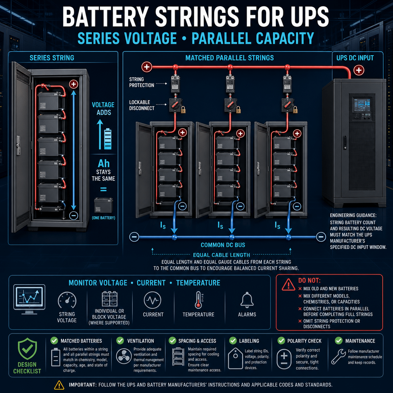
In a series connection, the positive terminal of one battery is connected to the negative terminal of the next. The individual battery voltages add together to create the DC voltage required by the UPS.
For example, connecting forty 12-volt batteries in series creates a nominal string voltage of:
40 batteries × 12 volts = 480 VDC nominal
The actual string voltage will vary with battery chemistry, state of charge, charging mode, temperature, load, and battery condition.
The string’s ampere-hour capacity does not add in a series connection. If each battery is rated at 100 Ah, the complete series string is nominally a 480-volt, 100-Ah battery string, not a 4,000-Ah string.
Commercial UPS systems may use long strings operating at several hundred volts DC. Vertiv documentation, for example, describes UPS strings made from series-connected batteries and warns that complete string voltage can reach potentially lethal levels. Installation and maintenance must therefore be performed by qualified personnel using the applicable electrical-safety procedures.
Series Determines Voltage
The number of cells or battery blocks in series is selected to match the DC input range of the UPS.
That number is not arbitrary. The UPS manufacturer establishes limits for:
- Nominal battery voltage
- Minimum discharge voltage
- Maximum charging voltage
- Permitted number of cells or blocks
- Battery chemistry
- Charger capacity
- Battery-test functions
- DC overcurrent protection
- Runtime configuration
Too few batteries may allow the DC voltage to fall below the inverter’s minimum operating threshold before the batteries have delivered their intended capacity.
Too many batteries may exceed the UPS, charger, capacitor, switching-device, or insulation rating, especially during charging, when string voltage is higher than nominal.
The correct series count must therefore come from the approved UPS and battery documentation. It should not be changed merely to obtain a different runtime.
Parallel Strings Determine Capacity and Runtime
When one series string cannot provide the required runtime or current, complete strings may be connected in parallel.
In a parallel arrangement:
- Each string has the same nominal voltage.
- The available ampere-hour capacity increases.
- Current is shared among the strings.
- Potential runtime increases.
- Available DC fault current also increases.
Two identical 480-volt, 100-Ah strings connected in parallel form a nominal 480-volt, 200-Ah battery bank. The voltage remains 480 volts because the strings are paralleled, while the capacity increases.
This relationship can be summarized simply:
- Batteries in series increase voltage.
- Complete strings in parallel increase capacity and current capability.
Actual runtime will not necessarily double when the number of strings doubles. Battery discharge rate, age, temperature, UPS efficiency, cell cutoff voltage, load level, and conductor losses all influence usable runtime.
Build Every Parallel String the Same Way
Parallel strings should be electrically equivalent.
Each string should normally have the same:
- Number of cells or monoblocs
- Battery manufacturer and model
- Chemistry
- Nominal capacity
- Age and service history
- Temperature exposure
- Connection method
- Conductor size
- Approximate cable length
- Protective-device arrangement
If one string has lower resistance, it may supply more discharge current and accept more charging current than the others. That string can run hotter and age faster, increasing the imbalance further.
Equal-length, equal-size cabling helps keep the resistance of the parallel branches similar. EnerSys specifically recommends using the same cable size and approximately the same cable length for each parallel string so that string resistance remains comparable. EnerSys UPS Battery Quick Start Guide
A balanced bus arrangement is also important. Connecting the UPS positive and negative leads in a way that favors the physically closest string can create unequal current paths. Commercial battery systems commonly use a properly designed common bus or coordinated connection geometry to achieve better sharing.
Do Not Mix Unlike Batteries
Installing new batteries into an aged string may look economical, but it can create an electrically mismatched system.
An older battery may have:
- Lower capacity
- Higher internal resistance
- Greater self-discharge
- Different charge acceptance
- Different terminal voltage under load
In a series string, every battery carries the same current. A weak battery can therefore reach its discharge limit before the rest of the string, restricting the capacity of the entire string.
During charging, voltage can also divide unevenly. A deteriorated unit may become overcharged or undercharged even when total string voltage appears normal.
Mixing different capacities, models, chemistries, or ages can make these problems worse. Unless the battery and UPS manufacturers provide a specific approved procedure, replacement should generally be performed at the complete-string or complete-bank level rather than by casually mixing dissimilar units.
Why the Weakest Battery Matters
Series-connected batteries carry the same current, but they do not necessarily have the same capacity or terminal voltage.
Suppose one battery in a long string has lost substantial capacity. During a discharge, that battery may reach a dangerously low voltage before the others. The UPS sees only total string voltage unless battery-level monitoring is installed, so the problem may remain hidden until runtime is needed.
A weak unit can cause:
- Reduced backup time
- Premature low-battery shutdown
- Excessive voltage imbalance
- Localized heating
- Reversal of a severely depleted cell
- Failed battery tests
- Unexpected loss of the entire string
This is why total string voltage alone is not a sufficient measure of battery health.
Protect Each Parallel String Individually
When several strings share a DC bus, each string should have appropriately engineered isolation and overcurrent protection.
Depending on the UPS design, this may include a:
- Battery circuit breaker
- Fused disconnect
- Battery disconnect cabinet
- Manufacturer-designed internal breaker
- Contactor coordinated with the UPS protection system
Individual protection serves several purposes:
- Isolates a faulted string
- Protects string conductors
- Allows maintenance on one string
- Prevents healthy strings from feeding excessive current into a failed parallel branch
- Provides a visible or controlled means of disconnection
Vertiv guidance states that parallel strings should be equipped with disconnecting means so maintenance on one string does not interfere with the others. It also recommends locating the battery circuit breaker close to the battery terminals and minimizing connection distance. Vertiv Liebert EXM UPS user manual
Protection must be rated for DC operation at the maximum possible system voltage and fault current. An AC-only breaker is not automatically suitable because interrupting DC presents different arc-extinguishing requirements.
Protective-device sizing and coordination must follow the UPS manufacturer’s instructions, the battery manufacturer’s limits, the engineered design, and applicable codes.
More Parallel Strings Are Not Always Better
Adding strings can increase runtime, but it also changes the electrical system.
Potential consequences include:
- Greater prospective fault current
- More complex protection coordination
- Increased charger demand
- Longer recharge time
- More connections that can loosen or corrode
- Greater monitoring and maintenance burden
- More difficult current sharing
- Increased floor-space and structural requirements
The UPS may also impose a maximum supported number of strings or external battery modules. Eaton, for example, publishes product-specific limits and requires equal external-battery-module quantities for UPS units in certain parallel arrangements to maintain equivalent runtimes. Eaton 9155 Parallel UPS user guide
The permissible number of strings must be verified for the exact UPS model rather than estimated from charger voltage alone.
Charger Capacity Must Match the Battery Bank
A larger battery bank requires more energy to recharge.
If parallel strings are added without considering charger capacity, the UPS may still operate but require an unacceptably long time to restore full charge after a discharge. This creates a period in which another outage could occur before the system has recovered its intended runtime.
The charger must also maintain the batteries at the correct voltage for their chemistry and temperature. Excessive charge voltage can accelerate corrosion, water loss, gas generation, or thermal problems. Insufficient voltage can leave the battery undercharged and promote capacity loss.
Configuration should account for:
- Battery chemistry
- Total bank capacity
- Desired recharge time
- Maximum charger current
- UPS auxiliary loads
- Generator compatibility
- Temperature compensation
- Manufacturer charging limits
Recharge performance should be evaluated following the design discharge, not just after a brief self-test.
Runtime Is Not Simply Ampere-Hours Divided by Amps
A rough energy estimate can be useful:
Nominal energy = nominal string voltage × ampere-hour capacity
However, this does not equal the energy available to the load.
Usable runtime is affected by:
- Discharge rate
- Battery terminal-voltage curve
- UPS low-voltage cutoff
- Battery age
- Temperature
- Inverter efficiency
- DC-cable voltage drop
- Battery imbalance
- Required end-of-life margin
- Actual critical load
Lead-acid capacity is particularly dependent on discharge rate. A battery rated over a long discharge period may deliver less than its nominal ampere-hour rating during a high-rate UPS discharge.
The correct approach is to use manufacturer discharge data or approved sizing software at the required load, end voltage, temperature, aging factor, and runtime.
Configure for End-of-Life Performance
A new battery bank should normally provide more than the bare minimum required runtime. Batteries lose capacity as they age, so a system sized to meet the requirement only on its first day may fall short well before its planned replacement date.
A sound design considers:
- Required runtime at end of life
- Battery aging factor
- Lowest expected battery-room temperature
- Future load growth
- UPS conversion losses
- Design margin
- Generator start and stabilization time
- Shutdown requirements if generation fails
Excessive oversizing has drawbacks, including cost, footprint, fault current, and recharge time. The goal is a justified margin, not unlimited capacity.
Temperature Strongly Affects Battery Performance
Battery-room temperature influences both available capacity and service life.
Low temperature generally reduces immediate discharge capacity. High temperature may temporarily improve available capacity but accelerates aging and can shorten service life significantly.
Strings connected in parallel should experience similar temperatures. A string near an air-conditioning outlet and another beside a warm UPS cabinet may age differently even if they were installed at the same time.
Good thermal design includes:
- Uniform airflow
- Avoidance of local hot spots
- Temperature monitoring
- Suitable ventilation
- Separation from heat-producing equipment where practical
- Charger temperature compensation when specified
- Alarm thresholds for abnormal conditions
Temperature sensors should be positioned according to the manufacturer’s guidance rather than simply placed at the coolest point in the room.
VRLA, Flooded Lead-Acid, and Lithium-Ion Strings
The meaning of a string remains similar across battery chemistries, but configuration and protection requirements differ.
Valve-regulated lead-acid
VRLA batteries are common in commercial UPS systems because they are compact and require less routine electrolyte maintenance than flooded cells. They remain sensitive to temperature, charging conditions, connection quality, and aging.
Flooded lead-acid
Flooded batteries may offer long service life and detailed cell-level inspection opportunities, but they require appropriate rooms, ventilation, spill management, maintenance access, and electrolyte procedures.
Lithium-ion
Lithium-ion UPS systems typically use modules combined into controlled strings with a battery-management system. The BMS monitors conditions such as cell voltage, temperature, current, and contactor state.
Lithium-ion modules should not be treated as interchangeable substitutes for lead-acid blocks. Charger behavior, communication, protection, fault response, and UPS compatibility must be specifically approved.
Battery Monitoring Should Go Below the String Level
Useful battery monitoring may include:
- Total string voltage
- Individual cell or monobloc voltage
- String current
- Float current
- Internal resistance or conductance trends
- Battery temperature
- Ambient temperature
- Ground-fault or insulation status
- Breaker position
- Connection resistance
- State of charge
- Discharge history
The most useful diagnostic information often comes from comparison and trending. One battery that gradually diverges from the rest may be more significant than an isolated reading that remains within a broad limit.
Monitoring does not replace inspection, testing, or maintenance. It helps identify where closer investigation is needed.
Common Configuration Mistakes
Incorrect number of batteries in series
This can place the DC bus outside the UPS charging or operating range.
Unequal parallel strings
Different battery models, capacities, ages, or conductor resistance can produce uneven current sharing.
No individual string isolation
A faulted string may be fed by the remaining strings, and maintenance may require taking the entire battery bank out of service.
Adding strings without checking the charger
Runtime may increase, but recharge time may become unacceptable.
Sizing from nominal ampere-hours alone
This overlooks discharge rate, cutoff voltage, temperature, aging, and UPS efficiency.
Assuming equal voltage means equal health
Parallel strings can show the same terminal voltage while having very different capacity or internal resistance.
Replacing only visibly failed units
The remaining batteries may be near the same wear-out condition, leading to repeated failures and continued imbalance.
Ignoring cable resistance
Unequal cable lengths, conductor sizes, or termination quality can cause unequal loading.
Mixing battery chemistries
Different chemistries require different charging, monitoring, and protective behavior.
Closing a battery breaker without checking voltage and polarity
A voltage mismatch or reversed connection can produce extreme current and catastrophic damage.
Commissioning a Commercial UPS Battery Bank
A formal commissioning process should verify both the design and the installation.
Typical checks include:
- Confirm the approved battery model, chemistry, quantity, and series count.
- Verify that every parallel string has the same configuration.
- Inspect batteries for shipping or installation damage.
- Confirm polarity at the battery, string, cabinet, and UPS connections.
- Measure individual battery and complete-string voltages.
- Compare open-circuit voltage spread before final connection.
- Verify cable size, routing, identification, and approximate branch equality.
- Confirm terminal torque using the battery manufacturer’s specified values.
- Check barriers, terminal covers, grounding, ventilation, and working clearances.
- Verify each string’s protective device and DC interrupting rating.
- Confirm UPS battery settings, capacity, cell count, and charging parameters.
- Check monitoring and temperature sensors.
- Verify breaker-status and alarm signals.
- Perform manufacturer-approved functional and runtime testing.
- Record baseline voltage, temperature, resistance, and conductance data.
The EnerSys commissioning guidance emphasizes checking voltage spread, using clean contact surfaces, applying specified terminal torque, confirming string voltage, and establishing the correct charge conditions before service. EnerSys UPS Battery Quick Start Guide
Safe Maintenance Requires More Than Opening the UPS Input
Turning off the AC supply does not necessarily remove the battery hazard. The battery bank remains an energized DC source capable of delivering very high current.
Even when a battery breaker is open, hazardous voltage may remain inside individual strings or across sections of the bank.
Maintenance planning should address:
- Lockout and isolation
- Verification of voltage
- DC-rated test equipment
- Insulated tools
- Appropriate personal protective equipment
- Removal of conductive jewelry
- Protection against accidental short circuits
- Correct lifting and handling
- Chemical and fire hazards
- Manufacturer-prescribed procedures
- Qualified-person requirements
Battery strings must never be treated as safe solely because the UPS display is off.
A Practical Configuration Example
Assume a UPS requires a nominal 480 VDC battery input and the approved design uses 12-volt, 100-Ah battery blocks.
One string would contain:
480 V ÷ 12 V per battery = 40 batteries in series
That creates one nominal:
480 V, 100 Ah string
If the approved runtime calculation requires 300 Ah, the design might use three identical strings in parallel:
3 strings × 100 Ah = 300 Ah nominal bank capacity
The resulting bank would contain:
- 40 batteries per string
- 3 parallel strings
- 120 batteries total
- 480 VDC nominal bank voltage
- 300 Ah nominal capacity
Each string would require coordinated conductors and suitable isolation and overcurrent protection. The charger, UPS configuration, bus, cabinet, monitoring, ventilation, and fault-current rating would all need to support the three-string arrangement.
This example illustrates the electrical relationships; it is not a substitute for manufacturer-approved sizing.
The Bottom Line
A battery string is a series-connected group of batteries that supplies the DC voltage required by a commercial UPS. Connecting complete, identical strings in parallel increases capacity and potential runtime without increasing nominal bank voltage.
A reliable configuration follows several core principles:
- Use the UPS manufacturer’s approved battery type and series count.
- Keep parallel strings electrically and thermally equivalent.
- Avoid mixing different models, capacities, ages, or chemistries.
- Give each string suitable DC-rated protection and isolation.
- Balance conductor resistance among parallel branches.
- Verify charger capacity and recharge time.
- Size runtime using real discharge data and end-of-life conditions.
- Monitor individual batteries as well as the complete string.
- Treat the battery bank as an energized high-voltage source at all times.
The best battery-bank design is not simply the arrangement with the most batteries. It is the configuration that delivers the required end-of-life runtime, shares current predictably, isolates faults safely, can be maintained without unnecessary risk, and remains fully compatible with the UPS that depends on it.