Call today (732) 560-9410 

Author: Brian Ribeiro

  • Single-Stage vs. Two-Stage Regenerative (RC) Blowers: Which One Is Right for You?

    Single-Stage vs. Two-Stage Regenerative (RC) Blowers: Which One Is Right for You?

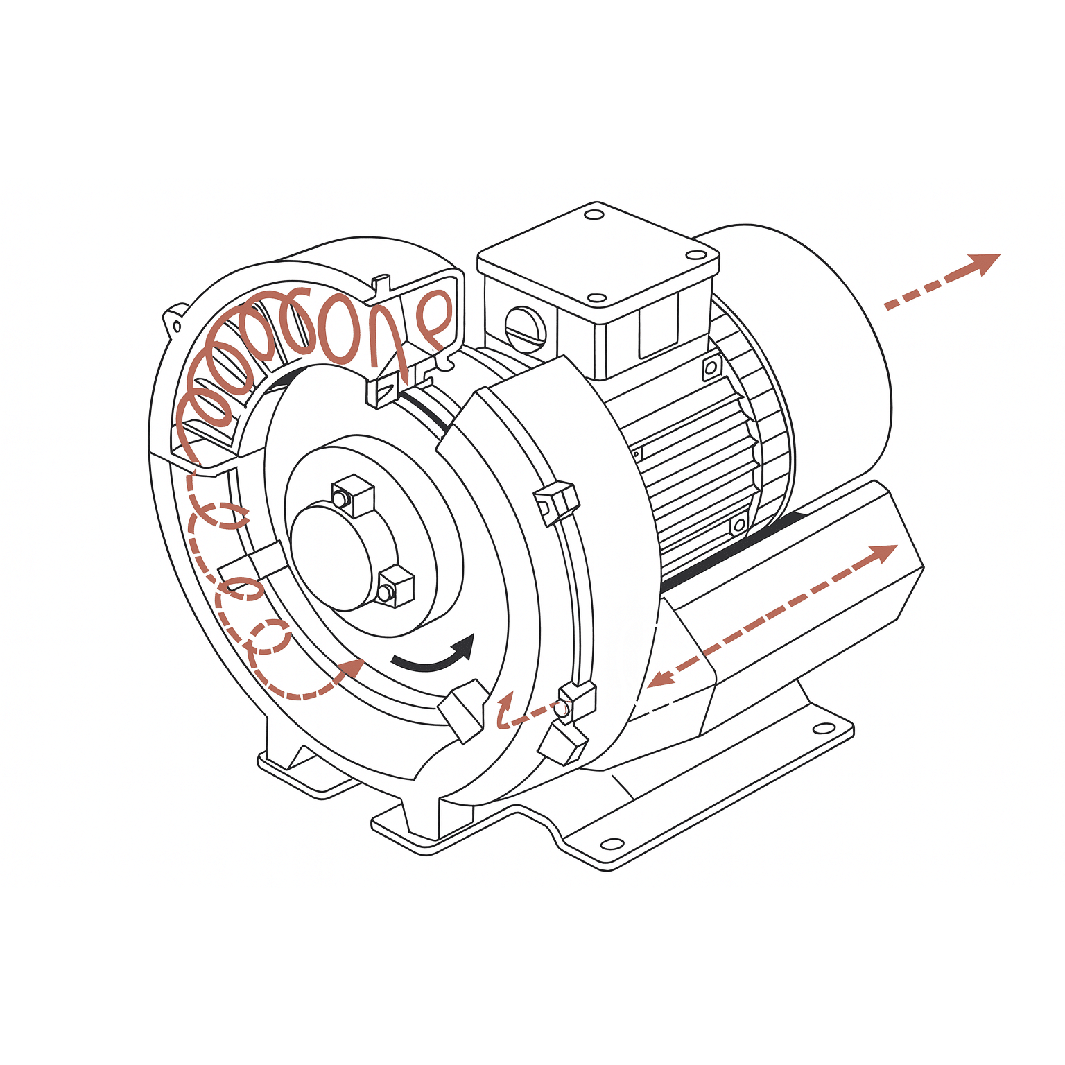
    Regenerative blowers (RC blowers) come in single-stage and two-stage designs. Choosing the right one depends on your application’s requirements for pressure, vacuum, and airflow.

    How They Differ

    Feature

    Single-Stage RC Blower

    Two-Stage RC Blower

    Air Path

    Air passes through one impeller stage

    Air passes through two impeller stages

    Pressure/Vacuum

    Lower pressure/vacuum

    Higher pressure/vacuum

    Airflow (CFM)

    Higher flow rate

    Lower flow rate at same motor power

    Complexity

    Simpler design

    Slightly more complex; still low maintenance

    Efficiency

    More efficient at low pressure/vacuum

    More efficient at higher pressure/vacuum

    When to Choose a Single-Stage Blower

    Ideal for:

    • High airflow, low-pressure applications
    • Air knives, cooling, drying, and aeration
    • Systems where pressure does not exceed ~3–4 psi or vacuum stays above ~10 inHg

    Benefits:

    • Higher CFM output
    • More energy-efficient at lower differential pressures
    • Often lower cost and simpler to install

    When to Choose a Two-Stage Blower

    Ideal for:

    • Higher pressure or vacuum requirements
    • Vacuum lifting, dense pneumatic conveying, wastewater backflushing
    • Systems needing up to ~7 psi or -14 inHg vacuum

    Benefits:

    • Greater pressure differential without oversizing the motor
    • Stable operation under load
    • Compact alternative to multiple single-stage units in series

    Quick Selection Tip:

    • If your process needs volume (CFM) more than pressure, choose single-stage.
    • If your process needs pressure or suction more than volume, choose two-stage.

    Application Examples

    Application

    Recommended Blower Type

    Tank aeration

    Single-stage

    CNC vacuum hold-down

    Two-stage

    Packaging suction pick-and-place

    Two-stage

    Air knife drying on conveyor

    Single-stage

    Wastewater filter backflush

    Two-stage

    Pneumatic transport (light materials)

    Single-stage

    Need Help Choosing?

    Many manufacturers provide performance curves for each model. Always compare against your system’s operating pressure, flow rate, and duty cycle to make the best choice.

  • How Electromagnetic Flowmeters Measure Conductive Liquids

    How Electromagnetic Flowmeters Measure Conductive Liquids

    Electromagnetic flowmeters, also known as magmeters, measure the flow of conductive liquids using Faraday’s Law of Electromagnetic Induction. Here’s how they work and why they’re ideal for certain applications:

    Basic Principle

    According to Faraday’s Law, when a conductive fluid flows through a magnetic field, it induces a voltage proportional to the flow velocity.

    Key Components

    1. Magnetic Coils
      • Generate a magnetic field across the pipe.
    2. Electrodes
      • Installed on opposite sides of the pipe wall to detect voltage.
    3. Flow Tube
      • Non-metallic and non-conductive lining (e.g., PTFE, rubber) to insulate the fluid from the electrodes.

    How It Works: Step by Step

    1. Magnetic Field Created
      • The flowmeter energizes the coils to produce a magnetic field perpendicular to the flow of the liquid.
    2. Conductive Fluid Moves Through Field
      • As the fluid (e.g., water, slurry, acid) flows through the pipe, it cuts through the magnetic field.
    3. Voltage Induced
      • The motion of the conductive liquid generates a voltage between the electrodes.
    4. Signal Processing
      • The induced voltage is directly proportional to the fluid velocity and is used to calculate volumetric flow.

    Key Characteristics

    • Only works with conductive liquids (minimum ~5 µS/cm conductivity)
    • No moving parts, reducing maintenance and pressure drop
    • Highly accurate (typically ±0.2–0.5% of reading)
    • Unaffected by temperature, pressure, or viscosity

    Common Applications

    • Water and wastewater
    • Pulp and paper slurries
    • Food and beverage fluids (e.g., dairy, juices)
    • Chemical processing
    • Mining and dredging slurries

    Limitations

    • Not suitable for non-conductive fluids like oils, gases, or deionized water
    • Requires full pipe condition for accurate measurement
    • Sensitive to electrical noise in poorly grounded systems


  • What are the ways to program an AC drive?

    What are the ways to program an AC drive?

    Programming a Fuji Electric FRENIC AC drive can be done in several ways depending on the model and user preference. Below are the most common methods used to configure and tune a FRENIC drive:

    Built-in Keypad (Digital Operator)

    Most FRENIC drives come with a built-in or detachable keypad for manual programming.

    Features:

    • 7-segment display or LCD screen (varies by model)
    • Scroll through parameters using arrow keys
    • Easily set motor data, acceleration/deceleration time, frequency limits, I/O logic, etc.

    Ideal For:

    • Quick setup or on-site adjustments
    • Users without a PC or software


    PC-Based Programming via FRENIC Loader Software

    Fuji Electric offers FRENIC Loader, a free Windows-based software tool.

    Features:

    • View, edit, and save parameter sets
    • Upload/download settings from drive
    • Monitor real-time performance (speed, current, voltage)
    • Save backups and clone settings to multiple drives

    Requirements:

    • PC with Windows OS
    • USB-to-RS485 converter or USB cable (depends on drive model)

    Ideal For:

    • Commissioning multiple drives
    • Advanced tuning and diagnostics
    • Creating parameter backups


    Smart Loader USB (For Some Models)

    Select FRENIC models support a Smart Loader USB interface, allowing parameter transfer via USB memory stick.

    Features:

    • Plug-and-play configuration transfer
    • Great for OEMs and field engineers
    • No PC needed on site

    Ideal For:

    • Rapid drive setup in the field
    • Preconfigured installations


    Remote Keypad / Digital Operator (Optional Accessory)

    External operator panels (e.g., TP-E1-E) allow you to program the drive remotely from outside an enclosure.

    Features:

    • Full keypad with display
    • Extended reach via cable
    • IP54 or better enclosures available

    Ideal For:

    • Control panels
    • Hazardous or hard-to-access drive installations


    Fieldbus or Network Communication

    Many FRENIC drives support network programming through fieldbus options like:

    • Modbus RTU
    • Ethernet/IP
    • Profibus
    • BACnet/IP (HVAC models)

    Features:

    • Set parameters and issue run/stop/frequency commands via PLC or SCADA
    • Monitor drive status remotely

    Ideal For:

    • Automated or integrated control systems
    • Facility-wide drive management\


    Preset Programs & Macros (Model-Dependent)

    Some FRENIC series (like the FRENIC-HVAC or FRENIC-MEGA) offer preloaded function sets or application-specific macros (e.g., pump, fan, conveyor).

    Features:

    • Quick setup using wizards
    • Logical groupings of parameters
    • Simplifies common applications

    Pro Tips for Programming FRENIC Drives:

    • Always start by entering motor nameplate data (parameter group F)
    • Use auto-tuning (if supported) for optimized motor performance
    • Save a parameter backup before making major changes
    • Use monitoring mode to view real-time performance during testing
    • Refer to the drive’s parameter manual for detailed descriptions and function codes
  • Top Industries That Rely on Flowmeters for Efficiency and Compliance

    1. Water and Wastewater
    • Purpose: Monitor potable water distribution, wastewater discharge, reuse water systems.
    • Why It Matters:
      • Regulatory compliance (e.g., EPA discharge limits)
      • Leak detection and water conservation
      • Billing and infrastructure planning
    1. Oil and Gas
    • Purpose: Measure flow of crude oil, natural gas, refined products.
    • Why It Matters:
      • Custody transfer (financial accuracy)
      • Leak detection and safety
      • Efficient refining and processing operations
    1. Chemical and Petrochemical
    • Purpose: Control the flow of various process chemicals, solvents, and gases.
    • Why It Matters:
      • Precise dosing for product quality
      • Hazardous material management
      • Batch process control
    1. Food and Beverage
    • Purpose: Measure water, ingredients, syrups, and CIP (clean-in-place) fluids.
    • Why It Matters:
      • Sanitary and hygienic standards (e.g., FDA, HACCP)
      • Consistent product quality and taste
      • Waste reduction
    1. Power Generation
    • Purpose: Measure feedwater, cooling water, steam, and fuel flow.
    • Why It Matters:
      • Thermal efficiency
      • Environmental compliance (e.g., emissions, water use)
      • Preventive maintenance
    1. Pharmaceutical and Life Sciences
    • Purpose: Control and monitor liquid and gas flows in production and lab processes.
    • Why It Matters:
      • Strict regulatory standards (e.g., GMP, FDA)
      • Product purity and consistency
      • Accurate batching and cleaning cycles
    1. HVAC and Building Automation
    • Purpose: Measure chilled water, hot water, steam, and air in HVAC systems.
    • Why It Matters:
      • Energy efficiency (e.g., LEED certifications)
      • Cost allocation in multi-tenant buildings
      • Performance monitoring
    1. Pulp and Paper
    • Purpose: Control water, chemicals, and pulp slurry flow rates.
    • Why It Matters:
      • Resource optimization
      • Consistency in product output
      • Wastewater compliance
    1. Agriculture and Irrigation
    • Purpose: Measure water usage in irrigation and livestock systems.
    • Why It Matters:
      • Conservation and drought management
      • Compliance with water usage regulations
      • Efficient fertilizer and pesticide application
    1. Semiconductor and Electronics
    • Purpose: Control ultrapure water, gases, and chemicals in cleanroom environments.
    • Why It Matters:
      • Precision at micro-scale
      • Contamination prevention
      • Tight process control


  • How to power HMIs in different applications?

    How to power HMIs in different applications?

    Powering an HMI (Human-Machine Interface) correctly is crucial for reliable performance across various applications. The power method depends on the HMI type, environment, and installation setup.


    1. Panel-Mounted Industrial HMIs


    Power Type:

    • Typically 24 VDC (most common for industrial use)
    • Some models support 100–240 VAC, but DC is preferred for noise immunity and safety


    How to Power:

    • Use a regulated 24 VDC power supply, ideally DIN-rail mounted
    • Isolate power from high-noise devices (e.g., VFDs, relays)
    • Add fuse or circuit breaker for short-circuit protection


    Applications:

    • Machine control panels
    • Process control systems
    • Industrial enclosures (IP65/IP66 front)
    1. Windows-Based HMIs or Industrial PCs


    Power Type:

    • Often require 90–264 VAC or 19–24 VDC, depending on form factor


    How to Power:

    • Connect to UPS-backed clean power source if used for critical control or SCADA
    • For panel PCs, use industrial-grade DC power supply with surge protection
    • Ensure grounding is solid to prevent ESD and communication issues


    Applications:

    • Control rooms
    • SCADA terminals
    • Large industrial displays and kiosks
    1. Portable or Mobile HMIs (Tablets, Handhelds)


    Power Type:

    • Rechargeable batteries or USB power adapters


    How to Power:

    • Use docking stations or USB-C adapters
    • Ensure runtime aligns with inspection/shift durations
    • Use explosion-proof enclosures in hazardous environments if needed


    Applications:

    • Maintenance rounds
    • Mobile diagnostics
    • Remote field operations
    1. Embedded HMIs with PLC Integration


    Power Type:

    • Typically 24 VDC


    How to Power:

    • Power from same source as PLC (with dedicated branch for isolation)
    • Use power conditioners or EMI filters if noise issues occur
    • Match current rating to HMI requirements (typically 0.5–2 A)


    Applications:

    • OEM machinery
    • Compact control panels
    • Modular PLC systems

    General Powering Tips for Any HMI

    Best Practice

    Why It Matters

    Use a dedicated power supply

    Prevents voltage dips from other devices

    Install EMI/RFI filtering

    Avoids display flickering or communication errors

    Protect with fuses or circuit breakers

    Prevents equipment damage

    Maintain proper grounding

    Reduces risk of shock and data issues

    Consider UPS backup

    Prevents data loss in power outages


  • UPS vs. Generator: Understanding the Differences in Backup Power

    UPS vs. Generator: Understanding the Differences in Backup Power

    Both UPS (Uninterruptible Power Supply) systems and generators provide backup power—but they serve very different purposes in terms of response time, power quality, and application. Understanding these differences is key to designing a resilient and efficient power protection system.

    What is a UPS?

    A UPS is an electronic device that provides instantaneous power to critical loads during a power disruption.


    Key Features:

    • Immediate response (0–10 milliseconds, often seamless)
    • Typically uses batteries (or capacitors) to store energy
    • Maintains power quality (voltage regulation, frequency stability)
    • Operates for short durations—enough to ride through short outages or allow orderly shutdown/start of generators


    Ideal For:

    • Data centers
    • Hospitals (for critical equipment)
    • Industrial automation controls
    • Telecommunications
    • Any sensitive load requiring zero downtime

    What is a Generator?


    A generator is a mechanical engine-driven system that converts fuel (diesel, natural gas, etc.) into electricity.


    Key Features:

    • Starts up after a delay (typically 10–60 seconds)
    • Provides extended backup power—can run for hours or days with sufficient fuel
    • Requires maintenance, ventilation, and fuel management
    • Does not condition power—needs ATS (Automatic Transfer Switch) and sometimes a UPS for critical loads


    Ideal For:

    • Commercial facilities
    • Factories and warehouses
    • Whole-building backup
    • Long-duration outages

    Comparison: UPS vs Generator

    Feature

    UPS

    Generator

    Response Time

    Instantaneous (milliseconds)

    Delayed (10–60 seconds typical)

    Backup Duration

    Short (minutes to ~1 hour)

    Long (hours to days)

    Power Source

    Batteries or flywheels

    Fuel (diesel, gas, etc.)

    Power Conditioning

    Yes (filters, regulates power)

    No (may need additional equipment)

    Maintenance

    Low (mainly battery checks)

    High (engine, fuel, oil, etc.)

    Noise & Emissions

    Silent, no emissions

    Noisy, produces exhaust

    Installation Needs

    Indoor, compact

    Requires space, exhaust, ventilation

    Best Use Case

    Critical electronics

    Whole-facility or long outages

    How They Work Together

    In mission-critical environments, UPS and generator systems are often used together:

    1. Power goes out
    2. UPS immediately supplies power to critical systems
    3. Generator starts within 10–60 seconds
    4. Once stable, the load is transferred to the generator
    5. UPS recharges and stands by for the next event

    Summary

    • UPS: Instant power, short-term, power quality = best for sensitive equipment
    • Generator: Delayed power, long-term, bulk energy = best for extended outages
  • Understanding UL 489 vs. UL 1077: Key Differences and Applications

    Understanding UL 489 vs. UL 1077: Key Differences and Applications

    When selecting circuit protection devices, it’s essential to understand the distinction between UL 489 and UL 1077standards. While both are defined by Underwriters Laboratories (UL), they apply to different types of circuit protection and serve different roles in an electrical system.

    UL 489 – Molded Case Circuit Breakers (MCCBs)

     Purpose:

    UL 489 covers branch circuit protection—the final leg of the power distribution system that directly serves loads (e.g., outlets, equipment).


    Characteristics:

    • Provides full protection against overloads and short circuits.
    • Must interrupt fault currents and clear the circuit safely under severe conditions.
    • Suitable for use as the primary protection device for circuits and connected equipment.


    Applications:

    • Panelboards
    • Industrial machinery
    • Lighting and receptacle circuits
    • Residential and commercial branch circuits


    Examples:

    • Molded Case Circuit Breakers (MCCBs)
    • Miniature Circuit Breakers (MCBs) rated to UL 489

    UL 1077 – Supplementary Protectors

    Purpose:

    UL 1077 applies to supplementary protectors, which are not intended for branch circuit protection but instead protect specific equipment or internal circuits.


    Characteristics:

    • Offers limited protection—primarily against overcurrents (not high fault currents).
    • Must be used in conjunction with a UL 489 device for branch circuit protection.
    • Not suitable for standalone protection of wiring or panel distribution.


    Applications:

    • Control circuits
    • Power supplies
    • Relays and solenoids
    • Motors, transformers (secondary side)
    • Industrial and commercial equipment internals


    Examples:

    • DIN-rail mounted breakers used inside machinery panels
    • Snap-in panel protectors for small equipment

    Key Differences at a Glance

    Feature

    UL 489

    UL 1077

    Protection Level

    Full branch circuit protection

    Supplemental/equipment-level protection

    Interrupting Capacity

    High (e.g., 10 kA, 22 kA, or more)

    Lower (usually < 2 kA)

    Application Location

    Distribution panels, load centers

    Inside machinery or equipment

    Suitable as Standalone Breaker

    Yes

    No

    Use with Branch Circuit

    Required

    Must be protected upstream by UL 489

    Common Form Factor

    MCCB, MCB

    DIN rail-mounted modular breakers

    Summary

    • Use UL 489 devices when you need primary protection for wiring, receptacles, and connected loads.
    • Use UL 1077 devices when adding supplementary protection for specific components within a larger protected circuit.


    Failing to apply these correctly can lead to code violations and unsafe installations.

  • Common Myths About Regenerative Blowers Debunked

    Common Myths About Regenerative Blowers Debunked

    Regenerative blowers (also known as side channel blowers) are widely used in industrial applications for their clean, oil-free air and low maintenance needs. However, several misconceptions persist that may prevent users from taking full advantage of their capabilities.


    Let’s debunk the most common myths:

    Myth 1: Regenerative blowers can’t produce enough pressure or vacuum.


    Reality:

    While regenerative blowers aren’t designed for high-pressure tasks like screw or piston compressors, they excel in low-to-medium pressure and vacuum applications—typically up to ~7 psi (pressure) or -14 inHg (vacuum). This makes them ideal for aeration, suction, drying, and material handling.

    Myth 2: They’re inefficient compared to other blower types.


    Reality:

    Regenerative blowers are very efficient in the right operating range—particularly when used for continuous, low-pressure airflow. With variable frequency drives (VFDs), efficiency and control can be further optimized. In many cases, they reduce energy and maintenance costs over time.

    Myth 3: They’re noisy.


    Reality:

    Modern regenerative blowers feature sound-dampening enclosures, precision balancing, and optimized impeller designs that significantly reduce noise. In well-designed systems, noise levels can be comparable to or even quieter than traditional compressors.

    Myth 4: They require constant maintenance.


    Reality:

    Unlike positive displacement blowers, regenerative blowers have no internal contact between moving parts. That means:

    • No lubrication required
    • No belts or gears to replace
    • Maintenance is typically limited to filter checks and bearing replacement after long intervals

    Myth 5: They can only be used in clean environments.


    Reality:

    With proper filtration and enclosure, regenerative blowers can be used in dusty, humid, and even corrosive environments. In fact, they’re often used in wastewater treatment, agricultural ventilation, and industrial vacuum systems.

    Myth 6: One size fits all.


    Reality:

    Regenerative blowers are available in a wide range of sizes, voltages, and configurations, including single-stage and two-stage models for higher pressure or vacuum needs. Selecting the right model ensures optimal performance.

    Bottom Line


    Regenerative blowers are quiet, reliable, oil-free, and energy-efficient when matched properly to the application. Don’t let outdated myths keep you from using one of the most versatile air movement technologies available today.

  • How to Specify an AC Drive Based on Application

    How to Specify an AC Drive Based on Application

    Specifying the right AC drive (also called VFD – Variable Frequency Drive) for your application is critical to achieving reliable performance, energy efficiency, and motor protection. Here’s a step-by-step guide to help you get it right:

    1.  

    Know Your Motor


    Collect basic motor nameplate data:

    • Horsepower (HP) or kilowatts (kW)
    • Voltage (V) – e.g., 230V, 460V, etc.
    • Full load current (FLA)
    • Frequency (Hz) – typically 50 or 60 Hz
    • Number of phases – usually 3-phase


    Tip: Always size the drive by current, not just horsepower.

    1.  

    Understand the Load Type


    Different loads demand different drive characteristics:

    Load Type

    Example Applications

    Drive Feature Needed

    Constant Torque

    Conveyors, crushers, compressors

    High torque at low speed

    Variable Torque

    Fans, pumps, blowers

    Energy-saving features, PID control

    Constant Horsepower

    Winders, spindles

    Wide speed range, torque limiting

    Tip: For fans/pumps, consider drives with built-in energy optimization and soft start.

    1.  

    Match the Environment


    Check the installation conditions:

    • Ambient temperature (e.g., derate if >40°C/104°F)
    • Dust/moisture → Need NEMA 12, IP54, or IP65 enclosure
    • Outdoor/explosive locations → Consider protective coatings or explosion-proof ratings
    1.  

    Determine Control Requirements


    What level of control or integration is needed?

    Feature

    Needed for…

    PID Control

    Pressure, flow, or temperature regulation

    VFD/PLC Integration

    Industrial automation

    Analog & Digital I/O

    Sensor/actuator feedback

    Network Communication

    BACnet, Modbus, Ethernet/IP, Profibus, etc.

    Tip: If you’re replacing a drive, check existing communication protocols.

    1.  

    Account for Duty Cycle and Overload


    Drives are rated for different duty types:

    • Light-duty (110% overload for 60 sec) – for HVAC fans/pumps
    • Heavy-duty (150% overload for 60 sec) – for conveyors, crushers, etc.


    Tip: Always check the drive’s current rating at your duty class.

    1.  

    Select Key Features Based on Application

    Application

    Must-Have Features

    HVAC Systems

    PID control, sleep mode, BACnet

    Pumps

    Soft start, anti-ramp, underload detection

    Conveyors

    Torque boost, flying start, braking options

    Cranes/Hoists

    Dynamic braking, high overload capacity

    Mixers/Agitators

    Low-speed torque, stall prevention

    1.  

    Plan for Future Needs

    • Consider expandable I/O or field-upgradable firmware
    • Choose drives that support energy logging, fault history, or remote monitoring
    1.  

    Check for Local Standards & Certifications

    • UL, CE, RoHS compliance
    • IEEE 519 for harmonic mitigation (especially in large systems)
    • NEC/CEC for installation guidelines

    Final Spec Checklist


    ✔ Motor HP/kW, voltage, FLA

    ✔ Load type (constant/variable torque)

    ✔ Duty cycle and overload rating

    ✔ Enclosure/environment rating

    ✔ Control & communication needs

    ✔ Application-specific features

    ✔ Compliance and safety requirements

  • Failure Modes of IGBTs and How to Prevent Them

    Failure Modes of IGBTs and How to Prevent Them

    IGBTs (Insulated Gate Bipolar Transistors) are robust power semiconductor devices, but they can fail under certain electrical, thermal, or mechanical stresses. Understanding common failure modes—and how to prevent them—is essential for designing reliable power electronic systems.

    Common Failure Modes in IGBTs

    1. Short Circuit Destruction

    Cause: Excessive short circuit current not interrupted in time

    Mechanism: High current causes extreme power dissipation and junction overheating within microseconds

    Prevention:

    • Use fast short circuit protection (<10 µs)
    • Ensure SCWT (Short Circuit Withstand Time) is not exceeded
    • Design low-inductance PCB layouts to reduce surge energy
    1. Latch-Up

    Cause: Excessive gate-emitter voltage or improper gate drive signals

    Mechanism: Parasitic thyristor structure turns on uncontrollably, leading to thermal runaway

    Prevention:

    • Never exceed maximum gate-emitter voltage (typically ±20V)
    • Use gate drivers with clamping and controlled dV/dt
    • Avoid slow switching at high currents
    1. Overheating / Thermal Overload

    Cause: Inadequate cooling, high switching losses, or continuous overcurrent

    Mechanism: Thermal stress degrades junctions, bond wires, and solder joints

    Prevention:

    • Maintain safe junction temperature (below rated Tj max)
    • Use appropriate heat sinks, thermal interface materials, and cooling systems
    • Monitor temperature with NTCs or thermal sensors
    1. Gate Oxide Breakdown

    Cause: Excess gate voltage or electrostatic discharge (ESD)

    Mechanism: Breakdown of the thin gate oxide layer, leading to leakage or complete failure

    Prevention:

    • Use gate voltage clamping (e.g., TVS diodes)
    • Handle with ESD protection protocols
    • Ensure gate drive circuits are properly designed
    1. Cosmic Ray-Induced Failures (Single Event Burnout)

    Cause: High-energy particles (typically in high-altitude or aerospace environments)

    Mechanism: Particle impact triggers parasitic thyristor latch-up

    Prevention:

    • Use IGBTs with improved ruggedness
    • For mission-critical systems, consider redundant design or SiC alternatives
    1. Bond Wire Lift-Off / Package Fatigue

    Cause: Repetitive thermal cycling

    Mechanism: Mechanical fatigue breaks internal connections

    Prevention:

    • Limit temperature swing during operation
    • Use modules with sintered connections or wire-bond-free designs
    • Apply soft switching techniques to reduce thermal cycling
    1. dV/dt-Induced Turn-On (Miller Effect)

    Cause: High collector-emitter voltage transients

    Mechanism: Miller capacitance induces gate voltage, turning the device on unintentionally

    Prevention:

    • Use negative gate voltage during off-state
    • Include gate resistors and Miller clamps in the driver

    Summary of Prevention Best Practices

    Risk

    Prevention Strategy

    Short Circuit

    Fast protection, SCWT awareness

    Latch-Up

    Proper gate drive design

    Overheating

    Thermal management, current limits

    Gate Oxide Breakdown

    Gate voltage clamping, ESD protection

    Cosmic Ray SEB

    Rugged modules, system-level redundancy

    Bond Wire Failures

    Temperature swing control, advanced packaging

    dV/dt Turn-On

    Negative gate bias, Miller clamp

    Final Thought

    While IGBTs are reliable when properly applied, most failures are avoidable with good circuit design, robust protection, and attention to thermal management. Investing in proper system integration and testing is key to maximizing device lifespan and system reliability.