
Power semiconductors are the backbone of modern electronics and power conversion systems. From variable frequency drives and renewable energy systems to electric vehicles and industrial automation equipment, devices such as IGBTs, MOSFETs, and power modules are expected to handle significant voltage and current while operating reliably for years.
However, every semiconductor has limits. Exceeding those limits—even briefly—can cause permanent damage, reduced reliability, or catastrophic failure. This is where the concept of Safe Operating Area (SOA) becomes critically important.
Understanding SOA helps engineers select the right devices, design robust circuits, and ensure long-term system reliability.
What Is Safe Operating Area (SOA)?
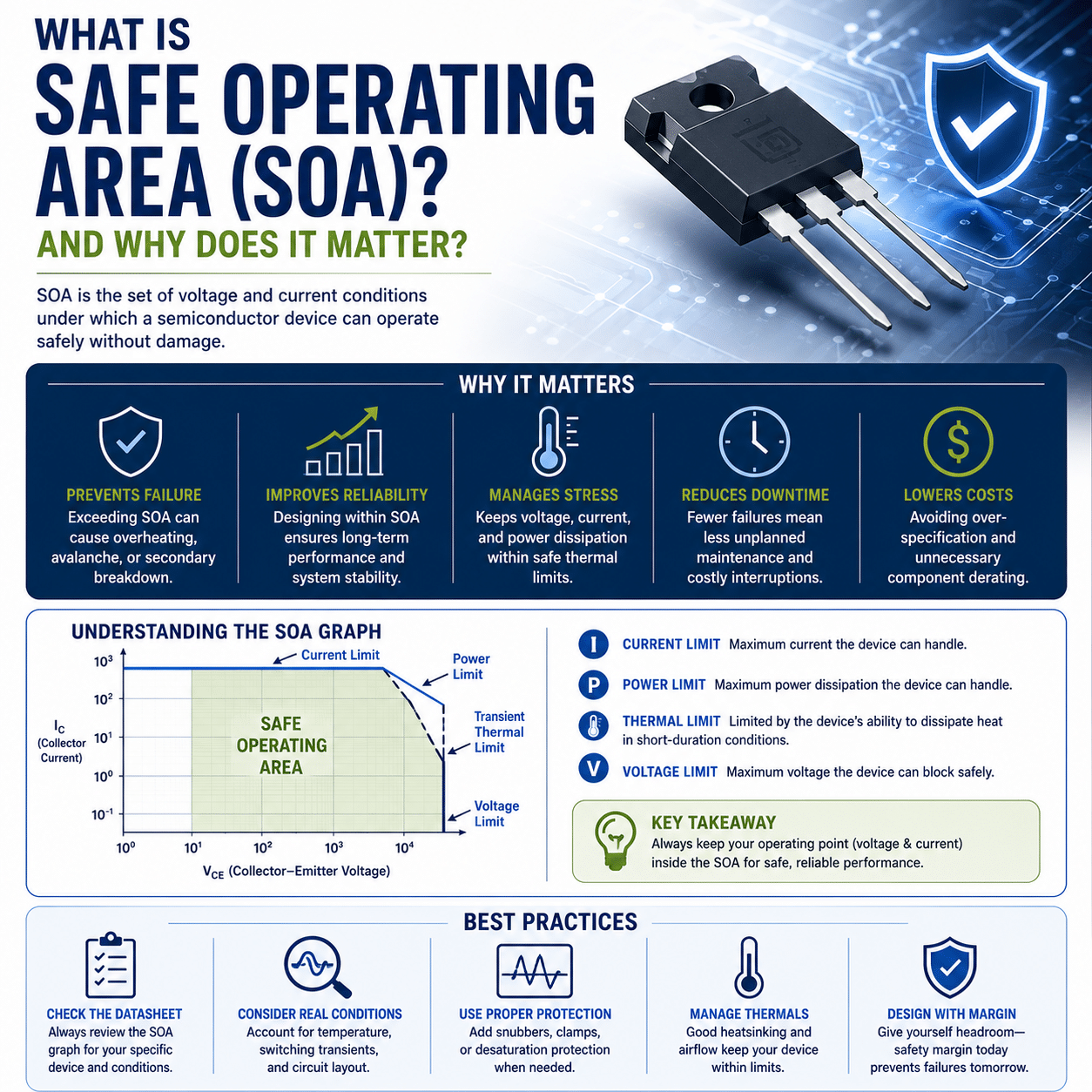
Safe Operating Area (SOA) defines the combinations of voltage, current, power, and time that a semiconductor device can safely withstand without sustaining damage.
Think of SOA as a performance envelope or boundary. As long as the device operates within this envelope, it should function safely and reliably under specified conditions.
When operation moves outside the SOA limits, the risk of:
- Overheating
- Junction damage
- Thermal runaway
- Secondary breakdown
- Device failure
increases significantly.
Manufacturers typically provide SOA information in device datasheets using graphs that illustrate safe operating limits under different operating conditions.
Why SOA Matters
Many engineers focus on a semiconductor’s maximum voltage and current ratings. While those specifications are important, they tell only part of the story.
A device may be rated for:
- 1200V maximum voltage
- 100A maximum current
But that does not necessarily mean it can safely handle 1200V and 100A simultaneously.
SOA accounts for the interaction between voltage, current, power dissipation, and duration of operation.
Without considering SOA, a design that appears acceptable on paper may experience:
- Premature failures
- Reduced reliability
- Excessive heating
- Unexpected shutdowns
- Costly downtime
Understanding the Key SOA Parameters
Several factors determine the safe operating limits of a semiconductor.
Voltage
Voltage stress is one of the primary limitations of power devices.
When voltage exceeds the semiconductor’s capability, breakdown can occur, potentially causing permanent damage.
SOA curves define how much voltage the device can tolerate under specific operating conditions.
Current
Higher current levels generate more heat within the device.
As current increases:
- Conduction losses increase
- Junction temperatures rise
- Thermal stress increases
SOA limits help define how much current can safely flow through the device at various voltages.
Power Dissipation
Power dissipation is calculated as:
Power = Voltage × Current
As power dissipation increases, so does internal heating.
SOA ensures the device remains within thermal limits that prevent junction temperatures from reaching damaging levels.
Time Duration
Many semiconductor devices can tolerate higher power levels for very short periods.
For example:
- A MOSFET may safely handle a large current pulse for microseconds.
- The same current level sustained for several seconds could cause failure.
This is why SOA graphs often include multiple curves representing different pulse durations.
Types of Safe Operating Area
Several SOA categories are commonly referenced in semiconductor datasheets.
Forward Bias Safe Operating Area (FBSOA)
FBSOA describes the safe operating limits when the device is turned on and conducting current.
It defines the combinations of:
- Voltage
- Current
- Pulse duration
that can be safely handled during normal operation.
FBSOA is especially important for:
- IGBTs
- Bipolar transistors
- Power modules
Reverse Bias Safe Operating Area (RBSOA)
RBSOA defines safe operating limits during turn-off events.
When a semiconductor switches off, it may simultaneously experience:
- High voltage
- High current
- Rapid voltage transitions
These conditions can create significant stress on the device.
RBSOA helps ensure the device can safely survive switching events without failure.
Short-Circuit Safe Operating Area (SCSOA)
Many modern power devices specify short-circuit withstand capability.
This defines how long the device can survive a fault condition before protection systems must respond.
For example:
- Many IGBTs are designed to withstand a short circuit for approximately 10 microseconds under specified conditions.
This brief window allows protection circuits to detect and clear faults.
SOA in IGBTs vs. MOSFETs
Although both technologies use SOA concepts, their behavior differs.
MOSFETs
MOSFETs generally:
- Switch very quickly
- Have strong avalanche capabilities
- Are commonly used at lower voltages
Their SOA is often limited by:
- Thermal effects
- Power dissipation
- Junction temperature
IGBTs
IGBTs are commonly used in:
- Motor drives
- Renewable energy systems
- Industrial power conversion
Their SOA considerations often include:
- Switching stress
- Thermal limits
- Short-circuit withstand capability
IGBTs are particularly sensitive to conditions that can lead to thermal runaway.
Thermal Considerations and SOA
Temperature plays a major role in safe operating limits.
As junction temperature increases:
- Current handling capability decreases
- Switching performance changes
- Device reliability declines
Many SOA curves are based on specific junction temperatures.
Operating at elevated temperatures effectively reduces the available SOA.
This is one reason why proper cooling systems are essential.
Common cooling methods include:
- Heat sinks
- Forced-air cooling
- Liquid cooling
- Thermal interface materials
What Happens When SOA Is Exceeded?
Operating outside the Safe Operating Area can produce several failure modes.
Thermal Runaway
As temperature rises, certain semiconductor characteristics change, leading to even greater heating.
This positive feedback loop can rapidly destroy the device.
Secondary Breakdown
Secondary breakdown occurs when localized hot spots form within the semiconductor.
These concentrated stress points can cause catastrophic failure even when average power levels appear acceptable.
Junction Damage
Excessive voltage or current can permanently damage the semiconductor junction structure.
Once damaged, the device may:
- Fail immediately
- Become unreliable
- Experience reduced performance
Reduced Lifespan
Even if immediate failure does not occur, repeated operation near or beyond SOA limits can accelerate aging mechanisms and shorten device life.
Designing for SOA Compliance
Engineers use several strategies to maintain operation within safe limits.
Select Adequate Safety Margins
Avoid designing systems that operate continuously at maximum ratings.
Additional margin helps accommodate:
- Component tolerances
- Temperature variations
- Transient events
Implement Fast Protection Circuits
Protection systems may include:
- Overcurrent protection
- Short-circuit protection
- Overtemperature protection
- Desaturation detection
Rapid fault detection helps prevent SOA violations.
Manage Thermal Performance
Effective thermal design is essential.
Consider:
- Heat sink sizing
- Airflow
- Cooling methods
- Thermal resistance paths
Control Switching Transients
Snubber circuits, gate driver optimization, and proper PCB layout can help reduce voltage and current spikes that may exceed SOA limits.
Reading an SOA Curve
A typical SOA graph plots:
- Current on the vertical axis
- Voltage on the horizontal axis
Multiple curves represent different pulse durations.
Areas inside the curve represent safe operation.
Areas outside the curve represent operating conditions that may damage the device.
Understanding these curves is an essential skill for power electronics engineers because they provide a more complete picture of device capability than simple maximum ratings.
Final Thoughts
Safe Operating Area (SOA) is one of the most important concepts in power semiconductor design. It defines the limits within which devices such as IGBTs, MOSFETs, and power modules can safely operate while maintaining performance and reliability.
By considering voltage, current, power dissipation, switching conditions, and temperature together, SOA provides a realistic view of a device’s true operating capability. Ignoring these limits can lead to overheating, thermal runaway, premature failures, and costly downtime.
Whether designing motor drives, renewable energy systems, power supplies, or industrial automation equipment, understanding and respecting SOA is essential for creating reliable, efficient, and long-lasting power electronic systems.