Call today (732) 560-9410 

Author: Brian Ribeiro

  • Noise Reduction Strategies for Regenerative Blower Installations

    Noise Reduction Strategies for Regenerative Blower Installations

    Regenerative blowers are widely used across industrial and commercial applications because of their compact design, oil-free operation, reliability, and ability to provide consistent airflow and vacuum performance. From pneumatic conveying and wastewater aeration to packaging equipment and medical systems, regenerative blowers play an essential role in many processes.

    However, like all high-speed air-moving equipment, regenerative blowers can generate noise during operation. If not properly managed, excessive noise can create challenges related to worker comfort, regulatory compliance, equipment perception, and overall facility environment.

    Understanding the causes of blower noise and implementing effective noise reduction strategies can significantly improve installation performance while maintaining airflow efficiency and system reliability.

    Why Regenerative Blowers Generate Noise

    Regenerative blowers operate by accelerating air through an impeller with multiple blades rotating at high speeds inside a specially designed housing. As air circulates through the blower stages, pressure and vacuum are generated through regenerative airflow principles.

    Several factors contribute to operational noise, including:

    • High-speed impeller rotation
    • Air turbulence
    • Motor noise
    • Mechanical vibration
    • Resonance within piping systems
    • Intake and discharge airflow noise

    The sound generated may vary depending on:

    • Blower size
    • Operating speed
    • System pressure
    • Installation environment
    • Mounting method
    • Piping design

    Understanding the primary noise source is the first step toward effective mitigation.

    Common Sources of Noise in Regenerative Blower Systems

    Noise does not always originate from the blower itself. In many installations, surrounding components and system design contribute significantly to overall sound levels.

    Airflow Noise

    Air movement through the intake and discharge ports is one of the most common noise sources.

    High-velocity airflow can create:

    • Turbulence
    • Whistling
    • Pulsation noise
    • Broadband airflow sound

    Restrictions or poorly designed piping may increase airflow turbulence and amplify noise levels.

    Mechanical Vibration

    Mechanical vibration from the blower and motor can transfer into:

    • Equipment frames
    • Floors
    • Pipe supports
    • Building structures

    This structure-borne vibration can create additional noise through resonance and amplification.

    Motor Noise

    The electric motor itself contributes operational sound through:

    • Bearing movement
    • Cooling fans
    • Electromagnetic hum
    • Rotational dynamics

    Variable frequency drive (VFD) operation may also introduce tonal noise depending on switching frequencies and motor design.

    Piping Resonance

    Long piping runs or unsupported ducts can resonate at certain frequencies, increasing perceived noise throughout the system.

    In some cases, piping systems act like acoustic amplifiers.

    Installation Environment

    Hard surfaces such as concrete walls, metal panels, and enclosed rooms can reflect and amplify sound waves, increasing overall noise exposure.

    Why Noise Reduction Matters

    Reducing blower noise offers several important benefits.

    Improved Workplace Comfort

    Lower noise levels create a more comfortable environment for operators and maintenance personnel.

    Regulatory Compliance

    Facilities may need to comply with:

    • OSHA workplace noise regulations
    • Local noise ordinances
    • Environmental standards

    Reduced Operator Fatigue

    Continuous exposure to high noise levels can contribute to fatigue and communication difficulties.

    Improved Equipment Perception

    Quiet operation often creates the perception of higher equipment quality and improved system performance.

    Better Facility Integration

    Noise reduction is particularly important in:

    • Medical facilities
    • Laboratories
    • Commercial buildings
    • Food processing facilities
    • Indoor manufacturing environments

    Effective Noise Reduction Strategies

    Several proven strategies can help reduce noise in regenerative blower installations.

    Install Intake Silencers

    One of the most effective methods for reducing blower noise is using intake silencers.

    Intake silencers help:

    • Reduce airflow turbulence noise
    • Lower intake sound pressure levels
    • Minimize high-frequency noise

    Properly sized silencers can significantly reduce airborne sound without substantially restricting airflow.

    Use Discharge Silencers

    Discharge silencers reduce noise generated as pressurized air exits the blower system.

    These silencers are especially beneficial in:

    • High-pressure applications
    • Pneumatic conveying systems
    • Aeration systems
    • Vacuum transport applications

    Selecting the correct silencer design is important to avoid excessive pressure drop.

    Isolate Vibration

    Mechanical vibration often contributes heavily to perceived noise levels.

    Vibration isolation techniques include:

    • Rubber isolation mounts
    • Spring isolators
    • Flexible connectors
    • Anti-vibration pads

    Proper isolation prevents vibration transfer into building structures and connected piping.

    Use Flexible Piping Connections

    Rigid piping can transfer vibration directly through the system.

    Flexible connectors help:

    • Reduce vibration transmission
    • Minimize resonance
    • Lower structure-borne noise

    Flexible connections are particularly important near the blower inlet and discharge ports.

    Optimize Piping Design

    Poor piping layouts can increase turbulence and resonance.

    Best practices include:

    • Avoiding abrupt transitions
    • Minimizing sharp bends
    • Using properly sized piping
    • Reducing airflow restrictions
    • Supporting piping adequately

    Smooth airflow reduces turbulence-related sound generation.

    Install Acoustic Enclosures

    In applications requiring substantial noise reduction, acoustic enclosures can provide significant sound attenuation.

    Well-designed enclosures may include:

    • Sound-absorbing insulation
    • Ventilation systems
    • Service access panels
    • Cooling airflow management

    However, thermal management is critical because regenerative blowers generate heat during operation.

    Apply Sound-Absorbing Materials

    Acoustic treatments within the installation area can help reduce reflected noise.

    Examples include:

    • Acoustic wall panels
    • Sound-absorbing ceiling materials
    • Insulated equipment rooms
    • Acoustic curtains

    Reducing sound reflection improves the overall acoustic environment.

    Proper Equipment Placement

    Blower location can significantly affect perceived noise levels.

    Whenever possible:

    • Place blowers away from occupied areas
    • Avoid corner installations that amplify sound
    • Use isolated equipment rooms
    • Separate blowers from reflective surfaces

    Strategic placement can reduce operator exposure without modifying the equipment itself.

    Optimize Blower Sizing

    Oversized blowers may operate inefficiently and generate unnecessary noise.

    Proper sizing helps:

    • Improve efficiency
    • Reduce excessive airflow velocity
    • Lower operating speeds
    • Minimize turbulence

    Selecting the correct blower for the application improves both acoustic and energy performance.

    Use Variable Frequency Drives (VFDs)

    Variable frequency drives allow blower speed control based on system demand.

    Benefits may include:

    • Lower operating speeds during reduced demand
    • Reduced airflow noise
    • Improved energy efficiency
    • Smoother system operation

    Careful VFD parameter setup can also help minimize motor-related tonal noise.

    Maintain the Blower System Properly

    Worn or damaged components can increase operational noise.

    Preventive maintenance should include:

    • Bearing inspections
    • Impeller inspection
    • Filter cleaning
    • Fastener checks
    • Alignment verification
    • Vibration monitoring

    Maintained equipment generally operates more quietly and efficiently.

    Understanding Noise Frequency Characteristics

    Different noise reduction methods target different frequency ranges.

    For example:

    • Silencers primarily address airborne airflow noise
    • Isolation mounts reduce low-frequency vibration
    • Acoustic foam absorbs mid- and high-frequency reflections

    A comprehensive noise reduction strategy often combines multiple approaches for the best results.

    Measuring and Evaluating Noise Levels

    Noise assessments help determine:

    • Primary noise sources
    • Frequency characteristics
    • Operator exposure levels
    • Effectiveness of mitigation efforts

    Sound measurements are commonly expressed in decibels (dBA).

    Evaluating both overall sound level and frequency spectrum provides better insight into appropriate mitigation strategies.

    Balancing Noise Reduction and Performance

    Noise reduction efforts should not compromise blower performance.

    Improper modifications may cause:

    • Excessive pressure drop
    • Reduced airflow
    • Increased motor loading
    • Thermal issues

    The goal is to achieve quieter operation while maintaining reliable system performance and efficiency.

    Fuji Electric Regenerative Blower Solutions

    Fuji Electric regenerative blowers are engineered for high performance, reliability, and efficient operation across demanding industrial applications.

    Our blower solutions are designed to support:

    • Stable airflow performance
    • Compact installation
    • Reliable continuous-duty operation
    • Industrial durability
    • Reduced maintenance requirements

    Fuji Electric also supports system optimization strategies that help improve installation efficiency, operational reliability, and overall acoustic performance.

    Noise generation is a common consideration in regenerative blower installations, particularly in facilities where operator comfort, environmental conditions, and regulatory compliance are important.

    Fortunately, effective noise reduction can often be achieved through a combination of:

    • Intake and discharge silencers
    • Vibration isolation
    • Proper piping design
    • Acoustic treatment
    • Equipment placement
    • Preventive maintenance

    By understanding the sources of blower noise and implementing appropriate mitigation strategies, facilities can create quieter, more efficient, and more reliable blower systems while maintaining the performance benefits regenerative blowers are known for.

  • Thermal Runaway in Power Semiconductors: Causes, Risks, and Prevention

    Thermal Runaway in Power Semiconductors: Causes, Risks, and Prevention

    Power semiconductors are the foundation of modern power electronics systems, enabling efficient energy conversion and motor control across applications such as industrial automation, renewable energy, electric vehicles, UPS systems, robotics, HVAC equipment, and data centers.

    As power densities continue to increase and systems become more compact, thermal management has become one of the most critical aspects of semiconductor reliability. One of the most serious thermal-related failure mechanisms in power electronics is thermal runaway.

    Thermal runaway can rapidly escalate from a localized temperature increase into catastrophic semiconductor failure, potentially damaging surrounding components and causing system downtime. Understanding the causes, risks, and prevention methods associated with thermal runaway is essential for improving reliability and long-term system performance.

    What Is Thermal Runaway?

    Thermal runaway occurs when increasing device temperature causes higher power dissipation, which then creates even more heat. This self-reinforcing cycle can quickly drive the semiconductor beyond safe operating limits.

    In many semiconductor devices, electrical characteristics change as temperature rises. Under certain operating conditions, higher temperatures may increase current flow or conduction losses, producing additional heat faster than the system can dissipate it.

    If heat generation exceeds the cooling system’s ability to remove heat, junction temperatures continue rising until permanent damage occurs.

    Thermal runaway can affect various power semiconductor devices, including:

    • IGBTs
    • MOSFETs
    • Diodes
    • SiC devices
    • Power modules
    • Bipolar transistors

    Why Thermal Runaway Matters

    Power semiconductor failures can have major consequences in industrial and commercial systems.

    Thermal runaway may result in:

    • Catastrophic semiconductor failure
    • Equipment shutdowns
    • Damage to surrounding circuitry
    • Reduced system reliability
    • Safety hazards
    • Increased maintenance costs
    • Production downtime

    In high-power applications such as motor drives, renewable energy inverters, and EV charging systems, preventing thermal runaway is critical for maintaining operational stability and equipment longevity.

    How Thermal Runaway Develops

    Thermal runaway typically occurs through a repeating feedback loop:

    1. Device temperature increases.
    2. Electrical losses increase.
    3. Additional heat is generated.
    4. Junction temperature rises further.
    5. The cycle accelerates.

    Without intervention, device temperatures can exceed safe operating limits in a very short time.

    The risk is especially high in high-current and high-switching-frequency applications where semiconductors already operate near thermal limits.

    Common Causes of Thermal Runaway

    Several factors can contribute to thermal runaway in power semiconductor systems.

    Inadequate Heat Dissipation

    One of the most common causes is insufficient cooling capacity.

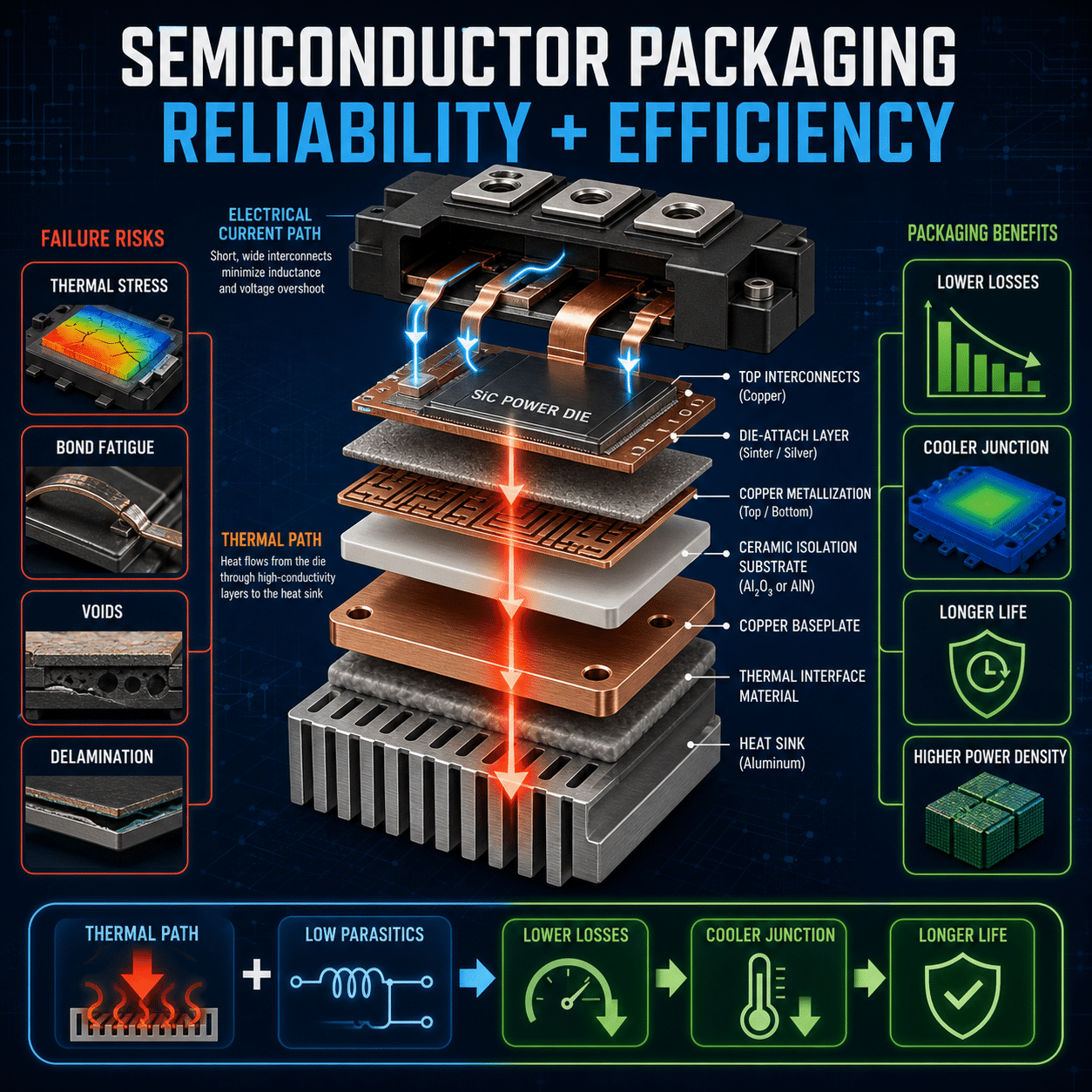
    Heat generated inside the semiconductor must be transferred efficiently through:

    • Device packaging
    • Thermal interface materials
    • Heat sinks
    • Cooling systems

    If thermal resistance is too high, heat accumulates inside the device.

    Common cooling-related issues include:

    • Undersized heat sinks
    • Poor airflow
    • Inadequate liquid cooling
    • Contaminated cooling surfaces
    • Improper thermal interface application

    Even minor cooling inefficiencies can significantly impact junction temperatures.

    Excessive Current

    Operating semiconductors beyond their rated current increases conduction losses and junction heating.

    Overcurrent conditions may result from:

    • Motor stalls
    • Short circuits
    • Overloads
    • Improper sizing
    • Fault conditions

    As current increases, power dissipation rises rapidly, increasing thermal stress.

    High Switching Frequencies

    Switching losses increase with frequency.

    Applications using high-frequency switching may generate significant heat due to:

    • Turn-on losses
    • Turn-off losses
    • Gate charging losses
    • Reverse recovery losses

    If switching losses exceed cooling capability, thermal runaway risk increases.

    Poor PCB or Busbar Design

    Thermal performance is heavily influenced by system layout.

    Poor designs may create:

    • Uneven current distribution
    • Hot spots
    • Increased parasitic inductance
    • Localized thermal stress

    Inadequate copper area or insufficient thermal pathways can worsen heat accumulation.

    Uneven Current Sharing

    In parallel semiconductor configurations, current imbalance can occur between devices.

    If one device carries more current than others, it heats more rapidly. Higher temperature may further alter electrical characteristics, causing even greater imbalance.

    This localized overheating can trigger thermal runaway in the overloaded device.

    Elevated Ambient Temperatures

    High surrounding temperatures reduce the cooling system’s ability to remove heat.

    Applications exposed to:

    • Outdoor environments
    • Enclosed cabinets
    • High-temperature industrial facilities
    • Poor ventilation

    may experience reduced thermal margins.

    Gate Drive Issues

    Improper gate drive design can increase semiconductor losses.

    Examples include:

    • Incorrect gate voltage
    • Slow switching transitions
    • Insufficient dead time
    • Excessive ringing
    • Gate instability

    Suboptimal switching behavior increases power dissipation and thermal stress.

    Degraded Thermal Interface Materials

    Thermal interface materials (TIMs) help transfer heat between the semiconductor and heat sink.

    Over time, TIM degradation may increase thermal resistance due to:

    • Drying
    • Pump-out effects
    • Mechanical fatigue
    • Improper mounting pressure

    Reduced thermal conductivity can significantly elevate junction temperatures.

    Semiconductor Characteristics and Thermal Behavior

    Different semiconductor technologies respond differently to temperature changes.

    Bipolar Devices

    Traditional bipolar transistors can exhibit negative temperature characteristics that increase thermal runaway susceptibility.

    MOSFETs

    MOSFETs generally have positive temperature coefficients at higher operating regions, which can help improve current sharing in parallel configurations.

    However, MOSFETs may still experience thermal runaway under certain conditions involving excessive switching losses or insufficient cooling.

    IGBTs

    IGBT thermal behavior depends on operating current and temperature range. Modern IGBT technologies are carefully engineered to improve thermal stability and reliability.

    SiC Devices

    Silicon carbide (SiC) semiconductors support higher temperature operation and improved efficiency, but thermal management remains essential due to extremely high power density.

    Risks Associated with Thermal Runaway

    Thermal runaway can produce severe consequences beyond simple device failure.

    Catastrophic Device Destruction

    Extreme temperatures may destroy:

    • Semiconductor junctions
    • Bond wires
    • Packaging materials
    • Solder connections

    Failure may occur explosively in severe cases.

    Secondary System Damage

    Failed semiconductors can damage:

    • Gate drivers
    • Bus capacitors
    • PCBs
    • Motors
    • Power supplies
    • Adjacent modules

    The resulting repair costs may be substantial.

    Reduced Reliability and Lifespan

    Even repeated near-runaway thermal cycling can accelerate:

    • Solder fatigue
    • Wire bond degradation
    • Material aging
    • Mechanical stress

    Over time, this reduces overall system reliability.

    Downtime and Operational Losses

    Unexpected semiconductor failures can create:

    • Production interruptions
    • Unplanned maintenance
    • Lost productivity
    • Service disruptions

    For mission-critical systems, downtime costs can be extremely high.

    Strategies for Preventing Thermal Runaway

    Preventing thermal runaway requires a comprehensive thermal management approach.

    Proper Thermal Design

    Effective cooling design is the first line of defense.

    Key considerations include:

    • Correct heat sink sizing
    • Adequate airflow
    • Liquid cooling when necessary
    • Low thermal resistance pathways
    • Proper enclosure ventilation

    Thermal simulations are often used during system design to verify cooling performance.

    Monitor Junction Temperatures

    Temperature monitoring helps detect abnormal operating conditions before failure occurs.

    Modern systems may use:

    • Embedded temperature sensors
    • Thermal shutdown protection
    • Real-time diagnostics
    • Predictive monitoring systems

    Active monitoring improves system protection and reliability.

    Use Appropriate Semiconductor Ratings

    Devices should be selected with adequate safety margins for:

    • Current
    • Voltage
    • Temperature
    • Switching frequency

    Operating continuously near maximum ratings reduces thermal margin and increases failure risk.

    Optimize Switching Performance

    Proper gate driver design minimizes switching losses.

    Optimization may include:

    • Gate resistor tuning
    • Controlled switching speeds
    • Dead-time optimization
    • Low-inductance layouts

    Efficient switching reduces overall heat generation.

    Improve Thermal Interface Quality

    Proper thermal interface application is critical.

    Best practices include:

    • Uniform mounting pressure
    • High-quality TIM materials
    • Clean mounting surfaces
    • Periodic inspection and replacement

    Reducing interface resistance improves heat transfer efficiency.

    Balance Parallel Devices Properly

    Parallel semiconductor designs should ensure balanced current sharing through:

    • Matched devices
    • Symmetrical layouts
    • Proper gate drive design
    • Current balancing techniques

    Uniform current distribution reduces localized overheating risk.

    Implement Protective Circuits

    Protective functions help prevent dangerous operating conditions.

    Common protections include:

    • Overcurrent protection
    • Thermal shutdown
    • Short-circuit protection
    • Desaturation detection
    • Soft shutdown circuits

    Fast fault response helps prevent thermal escalation.

    Maintain Cooling Systems

    Cooling system degradation can increase thermal resistance over time.

    Preventive maintenance should include:

    • Fan inspection
    • Filter cleaning
    • Coolant verification
    • Heat sink cleaning
    • Airflow monitoring

    Maintained cooling systems improve long-term reliability.

    The Importance of Thermal Simulation

    Thermal modeling and simulation are increasingly important in modern power electronics design.

    Simulation tools help engineers evaluate:

    • Junction temperatures
    • Airflow patterns
    • Heat distribution
    • Cooling effectiveness
    • Worst-case operating conditions

    Early thermal analysis helps identify risks before hardware deployment.

    Fuji Electric Semiconductor Solutions

    Fuji Electric develops advanced semiconductor technologies engineered for high efficiency, thermal performance, and long-term reliability across demanding industrial applications.

    Our semiconductor solutions support:

    • Industrial motor drives
    • Renewable energy systems
    • UPS platforms
    • HVAC systems
    • Electric mobility
    • Power conversion applications

    Fuji Electric technologies are designed to help improve thermal stability, reduce losses, and support reliable high-performance power electronics systems.

    Thermal runaway remains one of the most significant reliability risks in power semiconductor systems. As power densities increase and systems become more compact, effective thermal management becomes even more critical.

    Understanding the causes of thermal runaway ,  including inadequate cooling, excessive current, switching losses, and thermal imbalance ,  allows engineers to design safer and more reliable systems.

    Through proper thermal design, careful component selection, active monitoring, and preventive maintenance, facilities can significantly reduce the risk of thermal runaway while improving the performance and longevity of power electronic systems.

  • What Makes an HMI “Industrial Grade”? Key Specs to Look For

    What Makes an HMI “Industrial Grade”? Key Specs to Look For

    Human Machine Interfaces (HMIs) have become a critical part of modern industrial automation systems. From manufacturing plants and water treatment facilities to energy systems and packaging equipment, HMIs provide operators with real-time visibility and control over machines and processes.

    However, not all HMIs are designed for demanding industrial environments. While consumer-grade displays may function in controlled office settings, industrial applications require rugged, reliable, and purpose-built systems capable of withstanding harsh operating conditions.

    Understanding what makes an HMI truly “industrial grade” is essential when selecting the right solution for long-term reliability, safety, and performance.

    What Is an Industrial HMI?

    An industrial HMI is a specialized interface device that allows operators to monitor, control, and interact with industrial machinery and automation systems.

    Industrial HMIs typically provide:

    • Real-time process visualization
    • Alarm management
    • Equipment status monitoring
    • Data collection and trending
    • System diagnostics
    • Operator controls
    • Integration with PLCs, drives, and SCADA systems

    Unlike consumer electronics, industrial HMIs are engineered to operate continuously in environments exposed to:

    • Dust
    • Moisture
    • Vibration
    • Temperature extremes
    • Electrical noise
    • Chemicals
    • Washdown procedures

    The reliability requirements are significantly higher because downtime can directly impact production, safety, and profitability.

    Why “Industrial Grade” Matters

    In industrial environments, equipment failures can lead to:

    • Production interruptions
    • Lost revenue
    • Safety risks
    • Product quality issues
    • Increased maintenance costs

    A consumer-grade display or under-specified HMI may fail prematurely when exposed to harsh conditions. Industrial-grade HMIs are specifically designed to deliver stable operation under continuous industrial use.

    Choosing the right HMI can improve:

    • System uptime
    • Operator efficiency
    • Equipment longevity
    • Maintenance response times
    • Overall operational reliability

    Key Specifications That Define an Industrial-Grade HMI

    Several critical specifications separate industrial HMIs from standard commercial displays.

    Rugged Environmental Ratings

    One of the most important indicators of an industrial-grade HMI is its environmental protection rating.

    IP Ratings

    Ingress Protection (IP) ratings define resistance to dust and moisture.

    Common industrial ratings include:

    • IP65 ,  Dust-tight and protected against water jets
    • IP66 ,  Higher protection against powerful water jets
    • IP67 ,  Temporary immersion protection

    For washdown environments such as food processing or pharmaceuticals, higher protection ratings are often required.

    NEMA Ratings

    In North America, NEMA enclosure ratings are also commonly used.

    Examples include:

    • NEMA 4 ,  Indoor/outdoor protection against dust and water
    • NEMA 4X ,  Additional corrosion resistance
    • NEMA 12 ,  Protection against dust, dirt, and oil

    Proper environmental protection is essential for preventing contamination and premature equipment failure.

    Wide Operating Temperature Range

    Industrial facilities may experience:

    • High ambient temperatures
    • Cold outdoor installations
    • Heat generated by surrounding equipment

    Industrial HMIs are designed to operate reliably across wider temperature ranges than commercial displays.

    Typical industrial operating ranges may include:

    • 0°C to 50°C
    • -20°C to 60°C
    • Wider ranges for extreme environments

    Temperature tolerance is particularly important in:

    • Steel mills
    • Outdoor pumping stations
    • HVAC systems
    • Refrigeration facilities
    • Energy infrastructure

    Vibration and Shock Resistance

    Industrial machinery often generates continuous vibration and mechanical shock.

    Industrial-grade HMIs are designed with:

    • Reinforced internal components
    • Solid-state storage
    • Rugged mounting systems
    • Shock-resistant construction

    This helps maintain reliable operation in environments such as:

    • Manufacturing plants
    • Heavy equipment
    • Transportation systems
    • Material handling systems

    Without adequate vibration resistance, connectors, displays, and circuit boards may fail over time.

    High Display Brightness and Visibility

    Operators must be able to clearly view the HMI under varying lighting conditions.

    Industrial HMIs often feature:

    • High-brightness displays
    • Anti-glare coatings
    • Wide viewing angles
    • Enhanced contrast ratios

    Outdoor or brightly lit facilities may require sunlight-readable displays with brightness levels exceeding 1,000 nits.

    Good visibility improves:

    • Operator response time
    • Safety
    • Process monitoring accuracy
    • Overall usability

    Long Product Lifecycle Support

    Consumer electronics change rapidly, but industrial systems often remain in operation for 10 to 20 years or more.

    Industrial-grade HMIs typically offer:

    • Longer product availability
    • Stable hardware platforms
    • Long-term replacement support
    • Backward compatibility
    • Extended firmware support

    This is critical for minimizing redesign costs and maintaining system consistency over the life of the equipment.

    Industrial Communication Protocol Support

    Industrial automation systems rely on communication between devices.

    Industrial HMIs commonly support protocols such as:

    • Modbus TCP/IP
    • EtherNet/IP
    • PROFINET
    • EtherCAT
    • BACnet
    • CANopen
    • PROFIBUS

    Seamless communication with PLCs, AC drives, sensors, and SCADA systems is essential for reliable automation performance.

    Compatibility with multiple protocols increases system flexibility and simplifies integration.

    Continuous Duty Reliability

    Unlike office displays that may operate intermittently, industrial HMIs are often required to run continuously 24/7.

    Industrial-grade designs prioritize:

    • Long-life components
    • Thermal management
    • Fanless cooling designs
    • High MTBF (Mean Time Between Failures)

    Fanless systems are particularly valuable because they reduce:

    • Dust intake
    • Mechanical failure points
    • Maintenance requirements

    Continuous-duty reliability is essential in critical operations where downtime is costly.

    Touchscreen Durability

    Industrial touchscreens must withstand:

    • Frequent operator use
    • Gloves
    • Chemicals
    • Cleaning agents
    • Abrasion

    Industrial HMIs may use:

    • Resistive touchscreens
    • Capacitive touchscreens
    • Chemically strengthened glass
    • Multi-touch functionality

    Application requirements determine which touchscreen technology is best.

    For example:

    • Resistive screens work well with gloves and harsh conditions
    • Capacitive screens offer improved responsiveness and modern usability

    Electrical Noise Immunity

    Industrial facilities often contain:

    • Large motors
    • AC drives
    • Welding equipment
    • Switching power systems

    These environments generate significant electromagnetic interference (EMI).

    Industrial-grade HMIs are designed with shielding and filtering to maintain stable operation despite electrical noise.

    Proper EMI immunity helps prevent:

    • Communication errors
    • Screen freezes
    • Unexpected resets
    • Data corruption

    Data Logging and Edge Processing Capabilities

    Modern industrial HMIs increasingly support:

    • Data logging
    • Historical trending
    • Edge computing
    • Local analytics
    • Alarm history storage

    These capabilities help improve:

    • Troubleshooting
    • Process optimization
    • Predictive maintenance
    • Operational visibility

    Advanced HMIs may even support embedded scripting and lightweight industrial applications.

    Security Features

    As industrial systems become more connected, cybersecurity becomes increasingly important.

    Industrial HMIs may include:

    • User authentication
    • Role-based access
    • Encrypted communications
    • Secure remote access
    • Firmware integrity protection

    Security features help protect critical infrastructure and industrial operations from unauthorized access.

    Scalability and Expandability

    Industrial facilities evolve over time, so HMIs should support future expansion.

    Scalable HMIs may offer:

    • Multiple screen sizes
    • Expansion ports
    • Remote monitoring support
    • Web-based visualization
    • Cloud connectivity

    Flexible platforms help reduce future upgrade costs and simplify system growth.

    Software Stability and Ease of Integration

    Reliable hardware is only part of the equation. Industrial-grade HMIs also require stable software platforms.

    Important software considerations include:

    • Intuitive development tools
    • Reliable runtime performance
    • Easy PLC integration
    • Alarm management tools
    • Data visualization capabilities
    • Remote maintenance support

    Ease of configuration can significantly reduce engineering and commissioning time.

    Selecting the Right Industrial HMI

    Choosing the best HMI depends on:

    • Environmental conditions
    • Application complexity
    • Operator requirements
    • Communication needs
    • Regulatory requirements
    • Long-term support expectations

    Facilities should carefully evaluate:

    • Environmental ratings
    • Display performance
    • Connectivity
    • Lifecycle support
    • Reliability history
    • Vendor support capabilities

    The lowest upfront cost may not provide the best long-term value in demanding industrial environments.

    Fuji Electric Industrial HMI Solutions

    Fuji Electric offers industrial HMI solutions designed for reliability, usability, and performance in demanding automation environments.

    Our HMI technologies support:

    • Industrial communication integration
    • Rugged operating environments
    • High-performance visualization
    • Automation system connectivity
    • Long-term operational reliability

    Fuji Electric solutions are engineered to help manufacturers improve operator visibility, streamline control systems, and support efficient industrial operations.

    Industrial HMIs play a vital role in modern automation systems, serving as the connection point between operators and industrial equipment. However, not all HMIs are built to withstand the demands of industrial environments.

    True industrial-grade HMIs are designed with rugged construction, environmental protection, long-term reliability, communication flexibility, and continuous-duty performance in mind.

    By understanding the key specifications that define industrial-grade performance, facilities can make more informed HMI selection decisions that improve uptime, simplify maintenance, and support long-term operational success.

  • Regenerative Loads: When Do You Need a Dynamic Braking Resistor?

    Regenerative Loads: When Do You Need a Dynamic Braking Resistor?

    Modern AC drive systems are designed to deliver precise motor control, energy efficiency, and reliable operation across a wide range of industrial applications. However, some applications create a unique challenge for variable frequency drives (VFDs): regenerative energy.

    When a motor slows down or is driven by the load itself, it can act like a generator and send energy back into the drive. If that energy is not properly managed, it can cause nuisance trips, overvoltage faults, or even equipment damage. One of the most common solutions is a dynamic braking resistor.

    Understanding when regenerative energy occurs ,  and when a braking resistor is required ,  is essential for designing reliable motion control systems.

    What Is a Regenerative Load?

    A regenerative load occurs when the mechanical system drives the motor faster than the commanded speed or when the motor rapidly decelerates. Instead of consuming power, the motor generates power and sends it back into the DC bus of the AC drive.

    As regenerative energy builds inside the drive, the DC bus voltage rises. If the voltage exceeds safe operating limits, the drive will typically trip on a DC bus overvoltage fault.

    Regenerative conditions commonly occur in applications with:

    • Rapid deceleration
    • High inertia loads
    • Overhauling loads
    • Vertical motion systems
    • Frequent stopping and starting
    • Continuous energy feedback from the process

    Common Applications That Create Regenerative Energy

    Several industrial applications are naturally regenerative due to the physics of the load.

    Conveyors with High Inertia

    Long conveyors transporting heavy products often store large amounts of kinetic energy. During deceleration, that energy must go somewhere. Without a braking method, the drive may experience overvoltage conditions.

    Centrifuges and Flywheel Loads

    High-speed rotating equipment stores significant rotational energy. Fast stopping times can generate large regenerative currents as the motor attempts to slow the system.

    Cranes, Hoists, and Elevators

    Vertical loads are among the most common regenerative applications. Gravity can drive the motor during lowering operations, continuously feeding energy back into the drive.

    Fans and Blowers

    Large fans may continue spinning due to airflow or momentum after a stop command. Applications with aggressive deceleration ramps can become regenerative.

    Unwind Systems

    In web handling and converting operations, tension-controlled unwind systems often operate in regenerative mode because the material roll drives the motor.

    What Happens Without Proper Braking?

    When regenerative energy cannot be dissipated or redirected, several issues may occur:

    • DC bus overvoltage trips
    • Unexpected downtime
    • Loss of process control
    • Excessive stopping times
    • Reduced system reliability
    • Potential stress on drive components

    In some cases, operators attempt to solve the issue by increasing deceleration times. While this can reduce regenerative energy, it may not meet process requirements where rapid stopping is necessary.

    What Is a Dynamic Braking Resistor?

    A dynamic braking resistor dissipates excess regenerative energy as heat.

    When the DC bus voltage rises above a predefined threshold, the drive activates a braking transistor (sometimes called a chopper transistor). The transistor directs excess energy into the resistor, where it is converted into thermal energy and safely dissipated.

    This allows the drive to:

    • Decelerate loads faster
    • Prevent overvoltage faults
    • Improve stopping performance
    • Maintain process control
    • Protect drive electronics

    Dynamic braking is one of the simplest and most cost-effective solutions for handling intermittent regenerative energy.

    How Dynamic Braking Works

    The process can be summarized in four basic steps:

    1. The motor begins decelerating.
    2. The motor generates regenerative energy.
    3. DC bus voltage inside the drive increases.
    4. The braking transistor switches energy into the resistor.

    The resistor absorbs and dissipates the energy as heat until the DC bus voltage returns to a safe range.

    Because the resistor converts energy into heat, proper sizing and ventilation are important considerations.

    When Do You Need a Dynamic Braking Resistor?

    Not every AC drive application requires a braking resistor. Several factors determine whether one is necessary.

    Fast Deceleration Requirements

    If the application requires rapid stopping times, regenerative energy increases significantly. The shorter the deceleration ramp, the greater the braking demand.

    Applications that need aggressive acceleration and deceleration cycles often benefit from braking resistors.

    High Inertia Loads

    Loads with large rotating masses store more kinetic energy. Even moderate deceleration rates can generate substantial regenerative power.

    Examples include:

    • Large fans
    • Crushers
    • Centrifuges
    • Heavy conveyors

    Vertical or Overhauling Loads

    Whenever gravity assists motion, the motor can easily become regenerative. Hoists, elevators, cranes, and winches frequently require braking solutions.

    Frequent Cycling

    Applications with constant start-stop operation can repeatedly generate regenerative energy. Over time, this can create recurring overvoltage faults without proper braking.

    Overvoltage Faults During Deceleration

    One of the clearest signs that braking may be required is repeated DC bus overvoltage trips during stopping.

    If extending deceleration time is not practical, a braking resistor may be the best solution.

    When a Braking Resistor May Not Be Necessary

    Some applications naturally dissipate energy through system losses and may not require external braking.

    Examples include:

    • Low inertia loads
    • Long deceleration times
    • Constant-speed applications
    • Systems with infrequent stopping

    Many modern AC drives can also use techniques such as flux braking or controlled deceleration to help manage smaller regenerative conditions.

    Dynamic Braking vs. Regenerative Drives

    While braking resistors dissipate energy as heat, regenerative drive systems return excess energy back to the power grid.

    Each approach has advantages depending on the application.

    Dynamic Braking Resistors

    Advantages:

    • Lower initial cost
    • Simpler installation
    • Effective for intermittent braking
    • Compact solution

    Considerations:

    • Energy is wasted as heat
    • Additional heat management may be required
    • Limited continuous braking capability

    Regenerative Drives

    Advantages:

    • Returns energy to the electrical system
    • Improved overall efficiency
    • Better for continuous regeneration
    • Reduced heat generation

    Considerations:

    • Higher initial cost
    • More complex system integration
    • May require harmonic mitigation considerations

    For many industrial applications with occasional deceleration events, dynamic braking remains the preferred solution due to its simplicity and cost effectiveness.

    Proper Braking Resistor Sizing Matters

    Selecting the correct resistor is critical for reliable operation.

    Important sizing factors include:

    • Motor horsepower
    • DC bus voltage
    • Braking torque requirements
    • Duty cycle
    • Deceleration time
    • Load inertia
    • Ambient temperature

    Undersized resistors can overheat or fail prematurely, while oversized systems may increase unnecessary cost.

    Thermal management is also important because braking resistors can generate substantial heat during operation.

    Improving Reliability in Regenerative Applications

    Proper system design can help minimize braking-related issues and improve long-term reliability.

    Best practices include:

    • Verify load inertia during system design
    • Avoid unnecessarily aggressive deceleration ramps
    • Ensure proper resistor ventilation
    • Follow manufacturer sizing guidelines
    • Monitor braking duty cycle
    • Consider regenerative drives for continuous energy feedback applications

    Understanding the behavior of regenerative loads early in the design process helps prevent nuisance trips and improves overall system performance.

    Fuji Electric AC Drive Solutions

    Fuji Electric offers advanced AC drive solutions designed to handle demanding industrial applications, including regenerative load conditions. Our drive technologies provide reliable motor control, flexible braking integration, and high-performance operation across a wide range of industries.

    Fuji Electric drives support:

    • Dynamic braking configurations
    • High-performance motor control
    • Fast response applications
    • High-inertia load management
    • Industrial automation systems
    • Energy-efficient operation

    Whether your application involves conveyors, cranes, fans, hoists, or heavy industrial machinery, Fuji Electric can help identify the right drive and braking solution to improve performance and reliability.

    Regenerative energy is a common challenge in many AC drive applications, particularly those involving rapid deceleration, high inertia, or overhauling loads. Without proper energy management, regenerative conditions can lead to overvoltage faults, downtime, and reduced system reliability.

    Dynamic braking resistors provide a practical and effective method for dissipating excess energy and maintaining stable drive operation. By understanding when regenerative braking occurs and selecting the appropriate braking solution, facilities can improve uptime, protect equipment, and optimize motion control performance.

    As industrial systems continue demanding faster speeds, greater precision, and higher efficiency, effective regenerative energy management will remain an essential part of modern AC drive system design.

  • Understanding Short-Circuit Ratings (SCCR) for Control Panels

    Understanding Short-Circuit Ratings (SCCR) for Control Panels

    Protect your equipment. Ensure compliance. Prevent catastrophic failure.

    What is SCCR?

    Short-Circuit Current Rating (SCCR) defines the maximum fault current a control panel can safely withstand without causing fire, explosion, or extensive damage. It’s expressed in kiloamperes (kA) and must meet or exceed the available fault current at the installation point.


    Why SCCR Matters

    Safety First
    An underrated panel exposed to high fault current can fail violently—putting personnel and equipment at serious risk.

    Code Compliance
    Standards like NFPA 70 (National Electrical Code) and UL 508A require proper SCCR marking and verification for industrial control panels.

    Avoid Costly Rework
    If a panel’s SCCR is lower than the available fault current, it may fail inspection—leading to redesigns, delays, and added cost.


    How SCCR is Determined

    SCCR is based on the lowest-rated component within the power circuit—unless specific tested combinations allow for higher ratings.

    Key factors include:

    • Overcurrent Protection Devices (OCPDs)
      Fuses and circuit breakers can significantly influence overall SCCR when properly selected.
    • Component Ratings
      Contactors, motor starters, terminal blocks, and drives all have individual SCCRs.
    • Tested Combinations
      Using manufacturer-tested combinations (per UL 508A Supplement SB) can increase the panel’s overall SCCR.


    Common Pitfalls

    Weakest-Link Limitation
    A single low-rated component can reduce the entire panel’s SCCR.

    Ignoring Available Fault Current
    Failing to calculate or verify available fault current at the installation site leads to mismatches.

    Improper Component Pairing
    Not all combinations of breakers, fuses, and components are rated to work together at higher fault levels.


    Using current-limiting devices or UL-tested component combinations can allow a control panel’s SCCR to exceed the rating of its lowest-rated individual component. A component SCCR applies only to an individual device, while a panel SCCR represents the overall short-circuit withstand rating of the entire assembled control panel under specified conditions.


    How to Increase SCCR

    Use Current-Limiting Fuses
    These can dramatically raise the effective SCCR by reducing let-through energy during a fault.

    Select High-SCCR Components
    Choose contactors, drives, and terminals with higher withstand ratings.

    Leverage Tested Assemblies
    Follow UL 508A Supplement SB guidelines for approved component combinations.

    Optimize Circuit Design
    Segment circuits or add protective devices to isolate and limit fault exposure.


    Best Practices

    • Verify available fault current early in the design phase
    • Match or exceed SCCR across all components
    • Clearly label panel SCCR per code requirements
    • Document calculations and component ratings for inspection


    SCCR isn’t just a specification—it’s a critical safeguard. Properly rated control panels protect people, ensure compliance, and prevent costly failures.

  • How UPS Scalability Impacts Total Cost of Ownership in AI Data Centers

    How UPS Scalability Impacts Total Cost of Ownership in AI Data Centers

    Scale intelligently. Control costs. Keep compute online.


    Why Scalability Matters in AI Environments

    AI data centers don’t grow linearly—they scale in bursts as new GPU clusters come online. A UPS that can expand in step with demand avoids overbuilding, reduces stranded capacity, and keeps capital aligned with actual load.


    Where Scalability Impacts TCO

    1) CapEx Efficiency (Pay-as-You-Grow)

    • Start with a right-sized frame; add power modules as racks come online
    • Defer capital until it’s needed; avoid idle kW
    • Simplify budgeting for phased AI deployments

    Result: Lower upfront spend and better capital utilization.


    2) Energy Efficiency Across Load Ranges

    • Modular systems keep each module near optimal load
    • Higher efficiency at partial load vs oversized monolithic units
    • Reduced losses lower cooling demand

    Result: Lower OpEx and improved PUE.


    3) Availability & Redundancy (N+1 at Every Stage)

    • Add redundancy per phase (e.g., N+1 per frame)
    • Hot-swappable modules enable maintenance without downtime
    • Isolate failures to a single module

    Result: Higher uptime and reduced risk of revenue-impacting outages.


    4) Footprint & Power Density

    • Consolidate capacity into compact frames
    • Free up white space for revenue-generating compute
    • Align with high-density AI rack designs

    Result: Better $/sq ft and higher compute density.


    5) Maintenance & Lifecycle Costs

    • Swap modules instead of full-system overhauls
    • Standardized spares reduce inventory complexity
    • Enable predictive maintenance via granular monitoring

    Result: Lower service costs and less downtime.


    6) Future-Proofing for AI Workloads

    • Rapid onboarding of new GPU clusters without re-architecting power
    • Support for higher rack densities (e.g., 30–100+ kW/rack)
    • Easier integration of new battery chemistries and firmware upgrades

    Result: Avoid costly retrofits as AI demand accelerates.


    Modular vs. Monolithic UPS (TCO Snapshot)

    Factor

    Modular UPS

    Monolithic UPS

    Upfront Cost

    Lower (phased)

    Higher (overprovisioned)

    Efficiency at Partial Load

    High

    Lower

    Scalability

    Incremental

    Limited/step changes

    Redundancy

    Flexible (N+1 per stage)

    Fixed

    Maintenance

    Module-level

    System-level

    Risk of Stranded Capacity

    Low

    High


    Best Practices for AI Data Centers

    • Design for growth blocks: Size frames for near-term expansion, not peak end-state
    • Standardize modules: Simplify spares and maintenance across sites
    • Target optimal loading (40–80%): Maximize efficiency and longevity
    • Plan redundancy early: Build N+1 (or 2N) into each expansion phase
    • Integrate monitoring: Tie UPS telemetry into DCIM for capacity and health insights


    UPS scalability directly shapes both CapEx and OpEx in AI data centers. Modular, pay-as-you-grow architectures reduce wasted capacity, maintain high efficiency, and deliver resilient uptime—lowering total cost of ownership while enabling rapid expansion.

  • How Temperature Affects Pressure Measurement Accuracy

    How Temperature Affects Pressure Measurement Accuracy

    Protect measurement integrity. Improve control. Avoid costly errors.


    Why Temperature Matters

    Pressure instruments are calibrated under specific temperature conditions. When process or ambient temperatures shift, sensor behavior changes—introducing measurement drift, reduced accuracy, and potential control issues.


    Key Temperature Effects on Pressure Measurement

    1. Sensor Drift

    Most pressure sensors (strain gauge, piezoresistive, capacitive) are sensitive to temperature. As temperature rises or falls, internal components expand or contract, causing output signals to shift—even if actual pressure remains constant.

    Impact: Inaccurate readings, especially in processes with wide temperature swings.


    1. Zero and Span Shift

    Temperature changes can affect:

    • Zero (offset): The baseline reading when no pressure is applied
    • Span (sensitivity): The scaling of output across the measurement range

    Impact: Misleading readings across the full range—not just at a single point.


    1. Fluid Property Changes

    Temperature alters fluid characteristics such as density and viscosity.

    • Liquids expand with heat, affecting static pressure
    • Gases follow temperature-pressure relationships (e.g., ideal gas behavior)

    Impact: Apparent pressure changes that reflect temperature—not actual system performance.


    1. Mechanical Stress on Components

    Thermal expansion and contraction in piping, impulse lines, and mounting hardware can introduce mechanical strain on sensors.

    Impact: False readings or long-term sensor damage.


    1. Electronics Performance Degradation

    Extreme temperatures can affect internal electronics, including signal processing and output stability.

    Impact: Increased noise, reduced reliability, or complete failure.


    How to Minimize Temperature-Related Errors

    Use Temperature-Compensated Transmitters
    Modern instruments include built-in compensation to correct for thermal effects.

    Install Proper Isolation

    • Use impulse lines, siphons, or cooling elements for high-temperature processes
    • Protect sensors from direct heat exposure

    Calibrate at Operating Conditions
    Whenever possible, calibrate instruments at or near actual process temperatures.

    Select the Right Sensor Technology
    Different sensor types perform better under specific temperature ranges—match the technology to the application.

    Monitor Ambient Conditions
    Avoid placing transmitters in areas with extreme or fluctuating temperatures.


    Best Practices

    • Verify operating temperature ranges during specification
    • Account for both process and ambient temperature effects
    • Include temperature considerations in maintenance and calibration schedules
    • Review manufacturer compensation curves and accuracy specs


    Temperature is one of the most common—and overlooked—sources of pressure measurement error. Addressing it upfront ensures accurate data, stable control, and long-term reliability.

  • Heat Management in Regenerative Blowers: Causes, Effects, and Best Practices

    Heat Management in Regenerative Blowers: Causes, Effects, and Best Practices

    Protect performance. Extend equipment life. Avoid unplanned downtime.


    Why Heat Management Matters

    Regenerative blowers (side-channel blowers) generate heat as a natural byproduct of compressing and recirculating air. Without proper thermal control, excess heat can reduce efficiency, damage components, and shorten equipment lifespan.


    Where the Heat Comes From

    Compression & Recirculation

    Air is repeatedly accelerated and compressed within the blower’s side channel. Each pass increases temperature—especially at higher pressure differentials.

    Key driver: Higher pressure = more compression cycles = more heat.


    Motor Losses

    Electrical losses in the motor (I²R losses, core losses) convert energy into heat.

    Key driver: Continuous operation near full load or poor ventilation.


    Friction & Mechanical Resistance

    Bearings and airflow resistance contribute to additional heat buildup.

    Key driver: Worn components or improper lubrication.


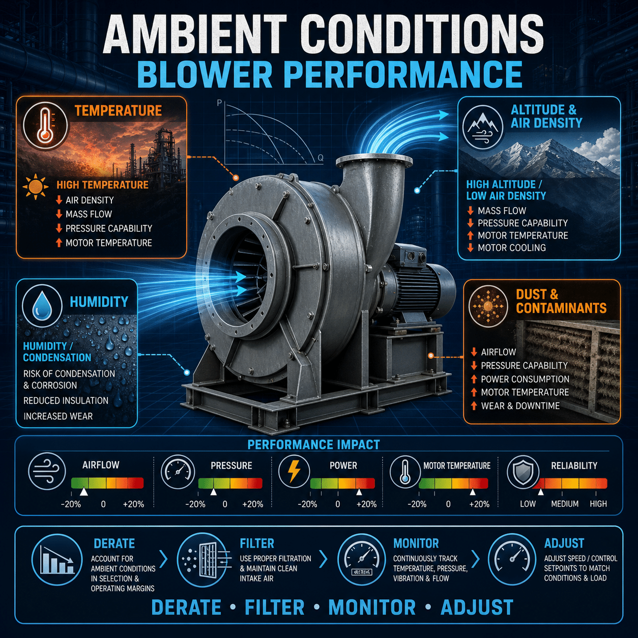
    Ambient Conditions

    High surrounding temperatures or confined spaces limit heat dissipation.

    Key driver: Poor airflow, enclosed installations, or hot environments.


    Effects of Excess Heat

    • Reduced Efficiency: Hot air is less dense, lowering blower performance
    • Thermal Expansion: Can affect internal clearances and increase wear
    • Seal & Bearing Degradation: Accelerates failure rates
    • Motor Overheating: Leads to insulation breakdown and shortened lifespan
    • Unexpected Shutdowns: Thermal protection trips interrupt operations


    Best Practices for Heat Management

    1. Operate Within Design Limits

    Avoid exceeding rated pressure or vacuum levels.

    • Stay within manufacturer performance curves
    • Oversizing or undersizing can both increase thermal stress


    1. Ensure Proper Ventilation
    • Install blowers in well-ventilated areas
    • Maintain adequate clearance around the unit
    • Avoid enclosed or heat-trapping environments


    1. Use Intake Air Management
    • Draw in cooler ambient air when possible
    • Avoid recirculating hot discharge air back into the intake
    • Consider ducting to isolate intake and exhaust paths


    1. Implement Variable Speed Control

    Using AC drives allows the blower to match output to demand.

    • Reduces unnecessary high-speed operation
    • Minimizes heat generation during partial load conditions
    • Improves overall system efficiency


    1. Monitor Temperature & Performance
    • Install temperature sensors on bearings and motor housings
    • Track trends to identify early signs of overheating
    • Integrate with HMI/SCADA for alerts and diagnostics


    1. Maintain Critical Components
    • Regularly inspect and service bearings
    • Ensure proper lubrication
    • Clean filters and air pathways to prevent restriction


    1. Consider Thermal Protection & Accessories
    • Thermal overload protection for motors
    • Cooling accessories (fans, heat shields, or enclosures) where needed
    • High-temperature-rated components for demanding environments


    Where Heat Management is Most Critical

    • Wastewater aeration systems
    • Pneumatic conveying
    • Industrial drying processes
    • Continuous-duty applications with high-pressure demand


    Heat is inevitable in regenerative blowers—but excessive heat is not. With proper design, operation, and maintenance, you can control thermal buildup, protect your equipment, and ensure reliable performance.

  • Understanding Reverse Recovery: Why Diode Behavior Matters in Power Modules

    Understanding Reverse Recovery: Why Diode Behavior Matters in Power Modules

    Reduce switching losses. Improve efficiency. Protect your system.


    What Is Reverse Recovery?

    When a diode switches from conducting (forward-biased) to blocking (reverse-biased), it doesn’t turn off instantly. Stored charge within the device must first be removed, creating a brief reverse current spike known as reverse recovery.


    What Happens During Reverse Recovery

    Key parameters:

    • Reverse Recovery Time (trr): Time required for the diode to stop conducting
    • Peak Reverse Current (Irrm): Maximum reverse current during recovery
    • Recovered Charge (Qrr): Total charge that must be removed

    Why it matters: The longer and larger the recovery, the greater the energy loss and stress on surrounding components.


    Why Reverse Recovery Impacts Power Modules

    1. Switching Losses

    During recovery, both current and voltage are present across the device—creating power loss.

    • Higher Qrr = higher energy dissipation
    • Reduces overall system efficiency


    1. Voltage Spikes & EMI

    Rapid current changes (di/dt) during recovery interact with circuit inductance, causing:

    • Voltage overshoot
    • Ringing and oscillations
    • Increased electromagnetic interference (EMI)


    1. Stress on Switching Devices

    In IGBT- or MOSFET-based systems, the switching device must handle the diode’s reverse recovery current.

    • Increased thermal stress
    • Higher risk of device failure
    • Reduced reliability over time


    1. Efficiency and Thermal Impact
    • More losses = more heat
    • Requires larger heat sinks or cooling systems
    • Limits power density in compact designs


    Where It Matters Most

    • Inverters (motor drives, HVAC systems)
    • UPS systems and power supplies
    • Renewable energy (solar, wind converters)
    • Electric vehicles and charging systems


    Technology Comparison

    Diode Type

    Reverse Recovery Performance

    Typical Use

    Standard PN Diode

    Slow, high Qrr

    Low-frequency applications

    Fast Recovery Diode

    Improved trr, moderate Qrr

    General power electronics

    Ultra-Fast Diode

    Low trr, lower Qrr

    High-frequency switching

    Silicon Carbide (SiC) Diode

    Near-zero reverse recovery

    High-efficiency, high-frequency systems


    Best Practices to Minimize Impact

    Use Low-Qrr or SiC Diodes
    Silicon carbide diodes virtually eliminate reverse recovery losses.

    Optimize Switching Speed
    Balance switching speed to reduce excessive di/dt and voltage spikes.

    Minimize Parasitic Inductance

    • Short, tight PCB layouts
    • Proper busbar design

    Add Snubber Circuits
    Dampen voltage spikes and ringing.

    Thermal Design Matters
    Ensure adequate cooling for both diodes and switching devices.


    Reverse recovery is a small-time event with big consequences. Managing diode behavior is essential for improving efficiency, reducing stress, and enabling high-performance power module design.

  • How to Build an Intuitive HMI Navigation Structure

    How to Build an Intuitive HMI Navigation Structure

    Simplify operator interaction. Reduce errors. Improve response time.


    Why Navigation Matters

    An HMI (Human-Machine Interface) is only as effective as its usability. Poor navigation slows operators down, increases training time, and raises the risk of mistakes—especially in high-pressure environments. A well-structured navigation system ensures operators can find critical information instantly and act with confidence.


    1. Start with Operator Workflows

    Design around how operators actually use the system—not how it’s engineered.

    • Map common tasks (startup, shutdown, alarms, troubleshooting)
    • Identify high-frequency vs. occasional actions
    • Prioritize speed for critical operations

    Goal: Reduce the number of steps to complete essential tasks.


    1. Use a Clear Hierarchical Structure

    Organize screens in a logical, layered format:

    • Level 1: Overview / Dashboard (plant or system status)
    • Level 2: Area or Process Views (e.g., pumps, lines, zones)
    • Level 3: Equipment Detail (specific assets, controls, diagnostics)

    Avoid deep nesting—operators should reach any critical screen within 2–3 taps.


    1. Keep Navigation Consistent

    Consistency builds muscle memory and reduces cognitive load.

    • Place menus in the same location on every screen
    • Use standard icons and naming conventions
    • Maintain uniform layouts and color usage

    Tip: If users have to “think” about navigation, it’s too complex.


    1. Prioritize Critical Information

    Not all data is equal—design accordingly.

    • Surface alarms, warnings, and system status prominently
    • Use visual hierarchy (size, color, placement) to guide attention
    • Avoid clutter—only show what’s actionable


    1. Design for Speed and Clarity

    Operators often work under time pressure.

    • Minimize clicks/taps for key actions
    • Use large, touch-friendly buttons
    • Ensure labels are clear and unambiguous

    Rule of thumb: No guesswork, no delays.


    1. Implement Smart Navigation Aids
    • Breadcrumbs: Show where users are within the system
    • Quick Access Buttons: For alarms, trends, and critical equipment
    • Search or Jump-To Functions: For large systems

    These tools reduce time spent navigating complex structures.


    1. Optimize Alarm Navigation

    Alarms should guide action—not overwhelm.

    • Link alarms directly to relevant equipment screens
    • Enable one-click navigation from alarm to root cause
    • Prioritize alarms by severity and urgency


    1. Design for Real-World Conditions

    HMIs are used in demanding environments.

    • Ensure readability in various lighting conditions
    • Use high-contrast color schemes
    • Avoid relying solely on color (support with text/icons)


    1. Test with Real Users

    Validation is critical.

    • Conduct usability testing with operators
    • Observe task completion time and error rates
    • Refine based on real feedback—not assumptions


    1. Plan for Scalability

    Your system will evolve—your navigation should too.

    • Design modular screen structures
    • Allow for easy addition of new equipment or processes
    • Maintain consistency as the system grows


    An intuitive HMI navigation structure reduces operator burden, speeds up decision-making, and improves overall system performance.