Flow Meters for Air
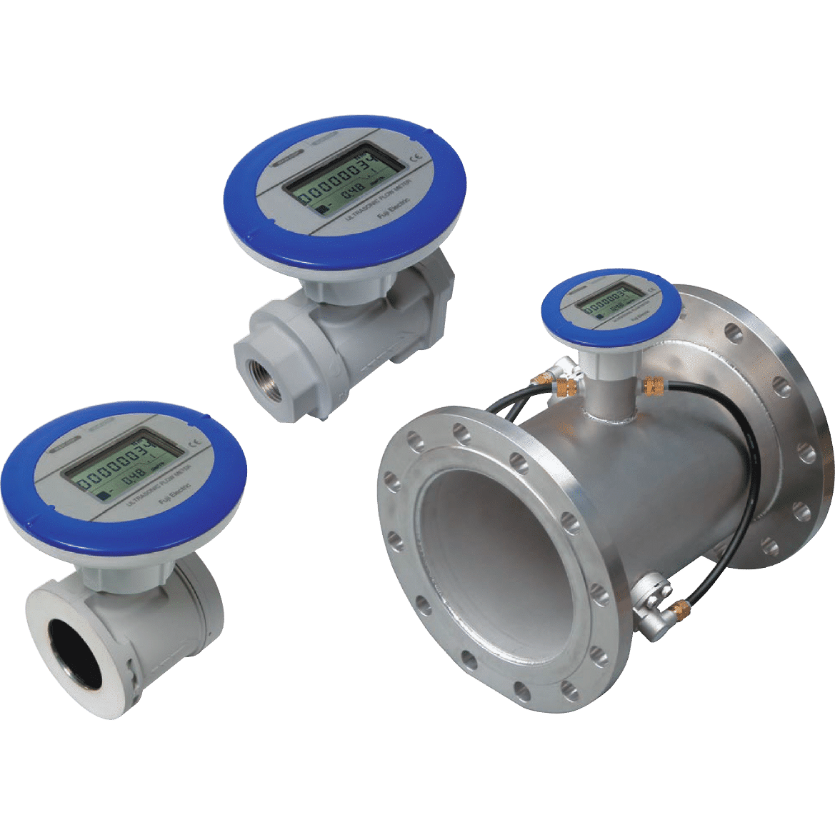
Fuji Electric’s Ultrasonic Flow Meter for Air utilizes ultrasonic measurement and features a built-in lithium battery, eliminating the need for power supply construction. Highly efficient due to zero pressure loss, the meter also includes forward/reverse measurement capability and a wide range of diameters.
Ideal For
- Ideal for control compressor
- Air leakage detection
- Visualization of the compressed air use and all air concentration measurement
- Energy saving.
Advantages
- Easy, quick and economical installation
- No wiring work (autonomous battery) or modification of the pipe configuration
- Clear viewing of compressed air and nitrogen consumption
- Fast real-time measurement on large rotating LCD display
- Early detection of air leaks
- Large measurement dynamic and excellent repeatability
- Measurement data you can trust
- Mass flow (Build-in pressure and temperature correction)
- Maximum flexibility and wide range of applications
- Bidirectional ultrasonic technology with no pressure loss
- Low maintenance
- No filter required. High resistance to contaminated fluids.
- Build to last in harsh industrial environments
- Robust and waterproof design

Measurement Principle
Two ultrasonic sensors are installed on each side of the flowmeter input and output. measurement principleWhen liquid flows (in the direction of the arrow shown on the diagram), difference of transit time by flow velocity occurs between sound waves generated from flow entrance and exit. This time lag is used for detecting the flow velocity of the fluid and calculating the volumetric flow according to cross-section area of the flow meter and flow velocity. Furthermore, this flowmeter is capable of converting into NORMAL flow rate by means of build-in pressure sensor in the flowmeter.


Specifications
| Pipe diameter (mm) | 25, 32, 40, 50, 65, 80, 100, 150, 200 | |||||||
| Power supply | 24 V DC ±10% or Built-in battery type (battery life : approx.10years at 20˚C) | |||||||
| Power consumption | 24 V DC, 1.5 W or less | |||||||
| Applicable fluids | Air (mainly air factory) or Nitrogen (25-80 mm diameter) | |||||||
| Teperature and humidity of fluid | 10°C to 60°C, RH 90% or less | |||||||
| Working pressure | 0 to 1 MPa (gauge pressure) | |||||||
| Range (actual flow rate) and accuracy | Diameter | Range (m3/h) | Accuracy | |||||
| ±2.0% of rate | ±0.6–3.5 m3/h | |||||||
| 25 | ±0.6–35 | ±3.5–35 m3/h | ±0.6–3.5 m3/h | |||||
| 32 | ±1.1–65 | ±6.5–65 m3/h | ±1.1–6.5 m3/h | |||||
| 40 | ±1.3–80 | ±8–80 m3/h | ±1.3–8 m3/h | |||||
| 50 | ±2.5–150 | ±15–150 m3/h | ±2.5-15m3/h | |||||
| 65 | ±4–240 | ±24–240 m3/h | ±4–24 m3/h | |||||
| 80 | ±5–300 | ±30–300 m3/h | ±5–30 m3/h | |||||
| 100 | ±10–500 | ±50–500 m3/h | ±10–50 m3/h | |||||
| 150 | ±24–1200 | ±120–1200 m3/h | ±24–120 m3/h | |||||
| 200 | ±40–2000 | ±200–2000 m3/h | ±40–200 m3/h | |||||
| Flow rate conversion accuracy | FWD 025–080 : ±2.5% or rate (at 500 kPa, 25°C, dry air) FWD 100–200 : ±2.0% or rate (at ≥ 300 kPa) |
|||||||
| Display | Main display | Forward or forward/reverse mode :
|
||||||
| Sub display |
|
|||||||
| Output signal (not available for battery-driven version) |
Current ouput | 4–20 mA DC (±0.5% FS), maximum resistance load 400Ω, maximum output current 22 mA Instantaneous flow rate, pressure, or temperature |
||||||
| Contact output |
|
|||||||
| Connection method | Ø25, Ø32 mm | Ø25 mm : Rc1, Ø32 mm : Rc1-1/4 | ||||||
| Ø40–Ø80 mm | Wafer (between JIS10K flanges) | |||||||
| Ø100–Ø200 mm | JIS10K flange | |||||||
| Materials of gas-contacting parts | Aluminum alloy, PPS, fluorosilicone rubber, etc. | |||||||
| Installation location | Indoor or outdoor (IP64 equivalent) | |||||||
| Storage temperature | -20°C to 70°C, non condensing | |||||||


